Data bus bridge and its working method

A data bus and working method technology, applied in the direction of bus network, data exchange through path configuration, electrical components, etc., can solve problems affecting system stability and reliability, incapable of data communication, complicated control process, etc., to achieve structural The effect of simplicity, strong anti-interference performance and high data transmission rate

Active Publication Date: 2007-08-15
CHANGZHOU TELEVIC KTK ELECTRONICS
View PDF1 Cites 60 Cited by
  • Summary
  • Abstract
  • Description
  • Claims
  • Application Information

AI Technical Summary

Problems solved by technology

[0010] The weak point of the above-mentioned prior art is: the above-mentioned transmission protocol processing module must be connected with a host through the PCI interface, and other working systems are connected with the ports of this module, and data communication or between each working system is carried out between the host computer and each working system. For data communication, the host computer is used to control the multi-port and multi-channel data flow of the module, which is inconvenient to install and the control process is complicated
In addition, once the host fails, the processing module cannot function, and data communication cannot be carried out among other working systems, thus greatly affecting the system stability and reliability

Method used


Image

  • Data bus bridge and its working method
  • Data bus bridge and its working method
  • Data bus bridge and its working method

Examples


Embodiment 1

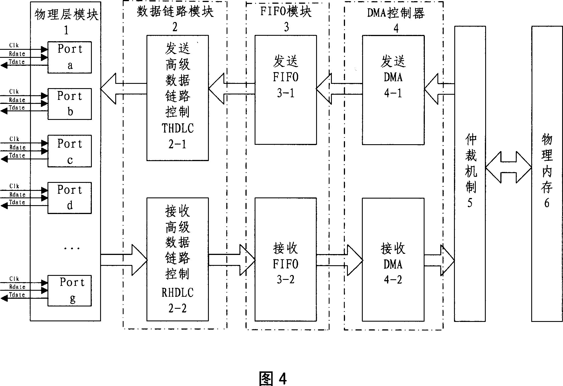
[0035] As shown in Figure 4, the data bus bridge is an application-specific integrated circuit ASIC (i.e. CPLD or FPGA, in other embodiments, also can adopt DSP or ARM), comprising: physical interface unit 1, data link unit 2, FIFO (multi-channel Data buffer management) unit 3 , DMA control unit 4 , arbitration mechanism unit 5 and physical memory unit 6 .

[0036] Still see Figure 4, the main functions of each unit are as follows:

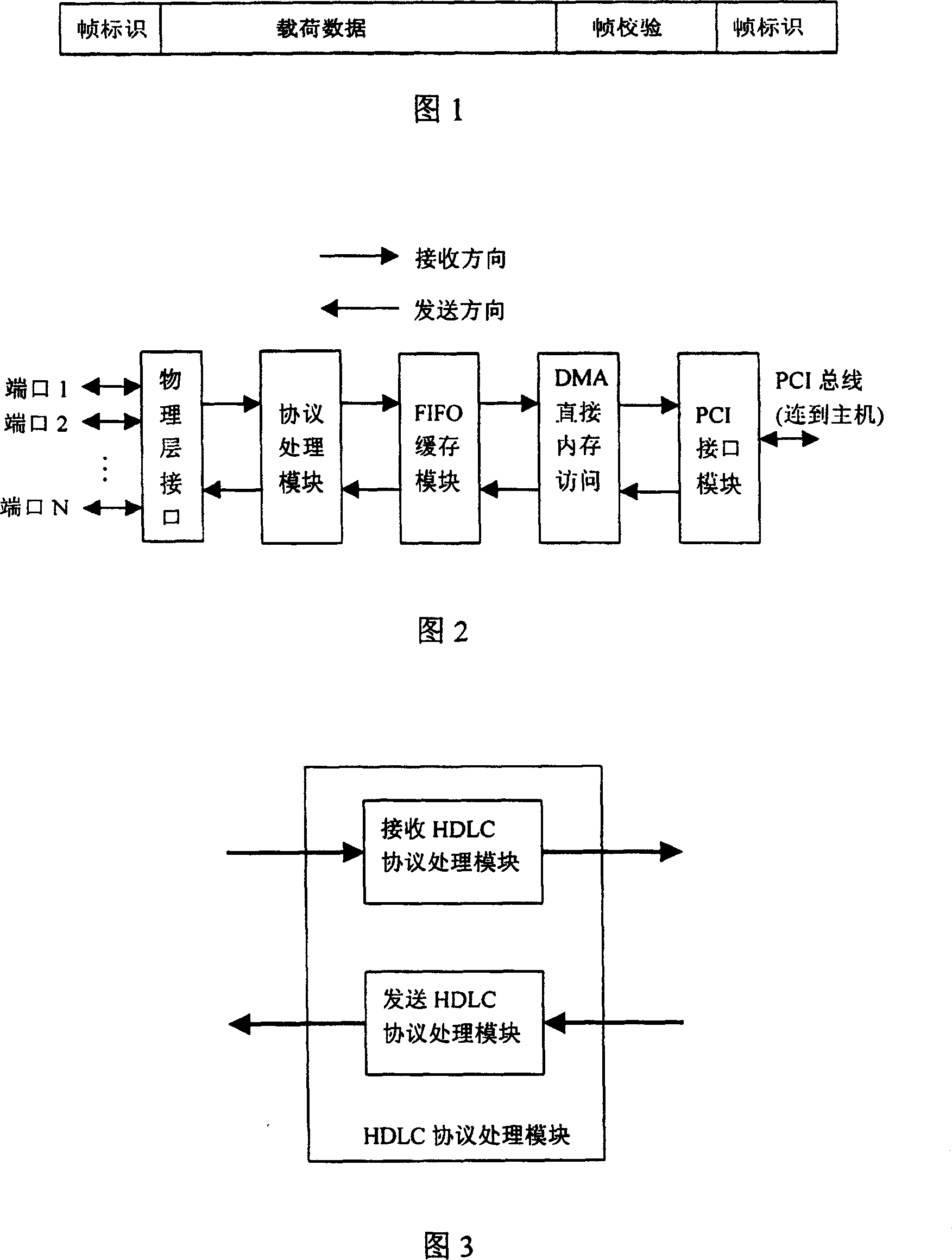
[0037] Physical interface processing unit 1: realize the mapping relationship between 8 physical links (Port a, Port b, Port c, Port d, Port e, Port f and Port g) and up to 128 logical channels, and convert the Data is redistributed according to different logical channels. Data of up to 16 logical data links can be transmitted on a physical link (a physical link refers to a wired or wireless transmission channel, excluding any switching nodes in the middle. Logical channels have a logical control relationship, because adjacent When transmitting da...


PUM


Abstract

The related data bus bridge comprises: a physical interface connected with external standard device to transmit data according to different logic channel, a data link unit to execute HDLC protocol for data on different logic channel, a FIFO unit for data buffer, an arbitrating mechanism unit to ensure physical interfaces exclusive visit the share data in memory and make the data read and write accord with protocol specification, and a DMA control unit to build high-speed data transmission between physical interface and physical memory. This invention is real-time and reliable, and fit to negotiate control device and monitor device.

Description

technical field [0001] The invention relates to the technical field of field bus, in particular to a data bus bridge and its working method. Background technique [0002] Screen door control system is a computer network system for real-time monitoring and management of screen doors. The system can feed back the relevant status of the corresponding screen door to the maintenance terminal and the main control computer PSC through each door machine control unit DCU through the network and the diagnostic interface, and then the maintenance terminal and the PSC perform parameter configuration on the system, query historical faults, Status record. A complete screen door control system includes: door machine control unit DCU, platform end control box PSL, main control computer PSC, vehicle control room operation indicator panel PSA, emergency control panel IBP, equipment monitoring system BAS, portable diagnostic terminal PTE, bus Networks and interfaces with other systems. [0...

Claims


Application Information

Patent Timeline
Patent Type & Authority Applications(China)
IPC IPC(8): H04L12/40H04L29/08
Inventor 戈建鸣陈冠华王云宽范国梁仇维斌刘振彬王建新
Owner CHANGZHOU TELEVIC KTK ELECTRONICS
Why Eureka
Try Eureka