Slurry mixture material distributing device and method
A technology of distributing equipment and slurry, applied in the direction of supply equipment, manufacturing tools, etc., can solve problems such as deformation, cracks, air bubbles, etc., and achieve rich decorative effects, ensure strength, and coordinate decorative effects
- Summary
- Abstract
- Description
- Claims
- Application Information
AI Technical Summary
Problems solved by technology
Method used
Image
Examples
no. 1 example
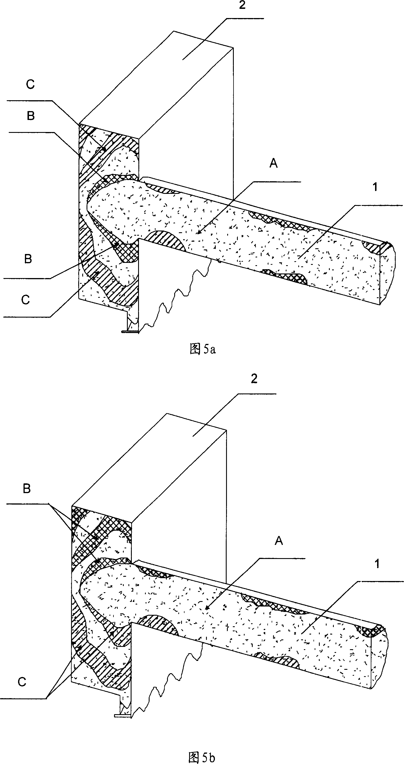
[0032] In this embodiment, the agitator 3 is arranged on the delivery channel of the distribution pipe 1 , and the distribution pipe 1 is detachably connected to the material storage box 2 . Specifically, each monochromatic slurry conveyed by the material distribution pipe 1 enters the storage box 2 after being processed by the agitator 3. After the mixed slurry in the storage box 2 is full, the storage box 2 is disassembled and replaced with another storage box. For box 2, continuous production can be realized by repeating the above process. The unloaded material storage box 2 is sent into subsequent processes such as drying, demoulding, and calcining to become ceramic tiles. The ceramic tiles produced in this embodiment have the characteristics of very coordinated layout decoration effects, and the overall pattern is beautiful and natural after multiple tiles are tiled.
no. 2 example
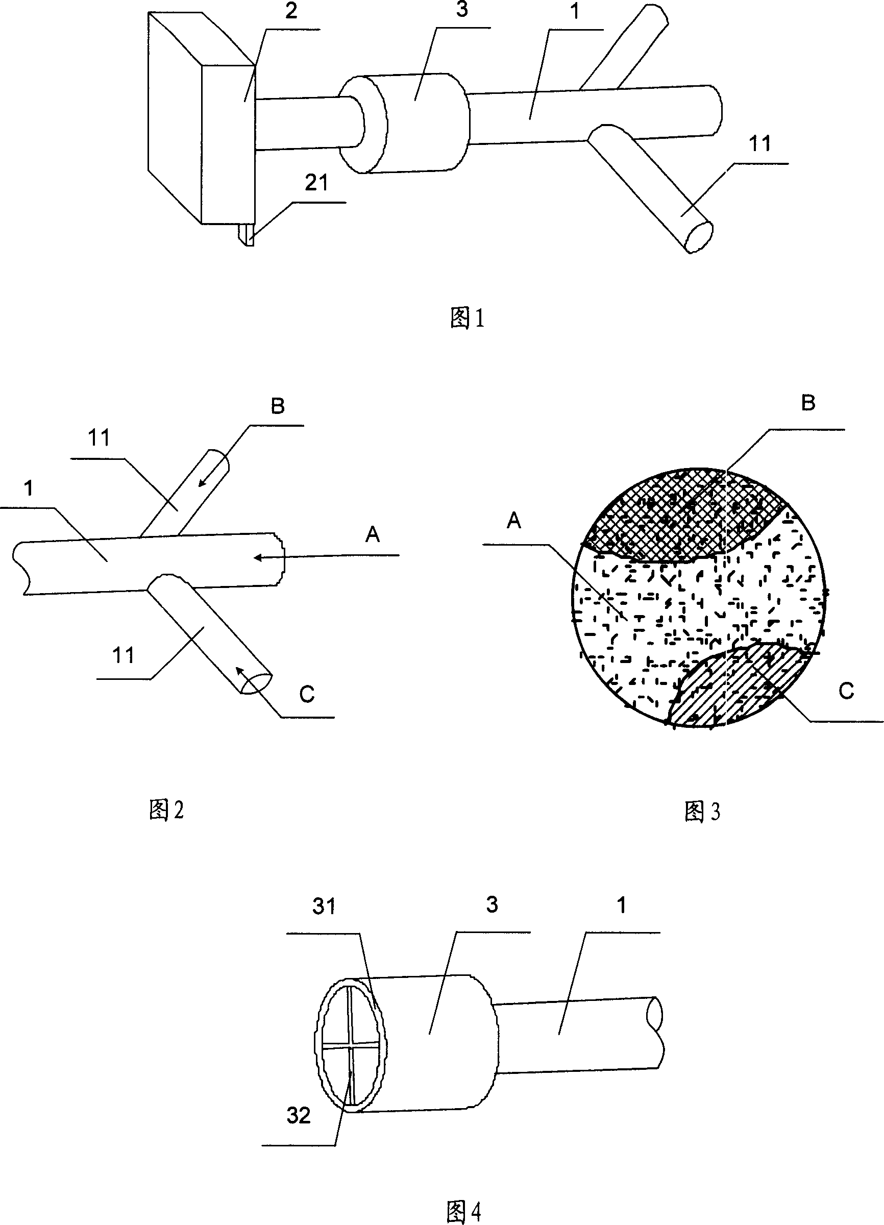
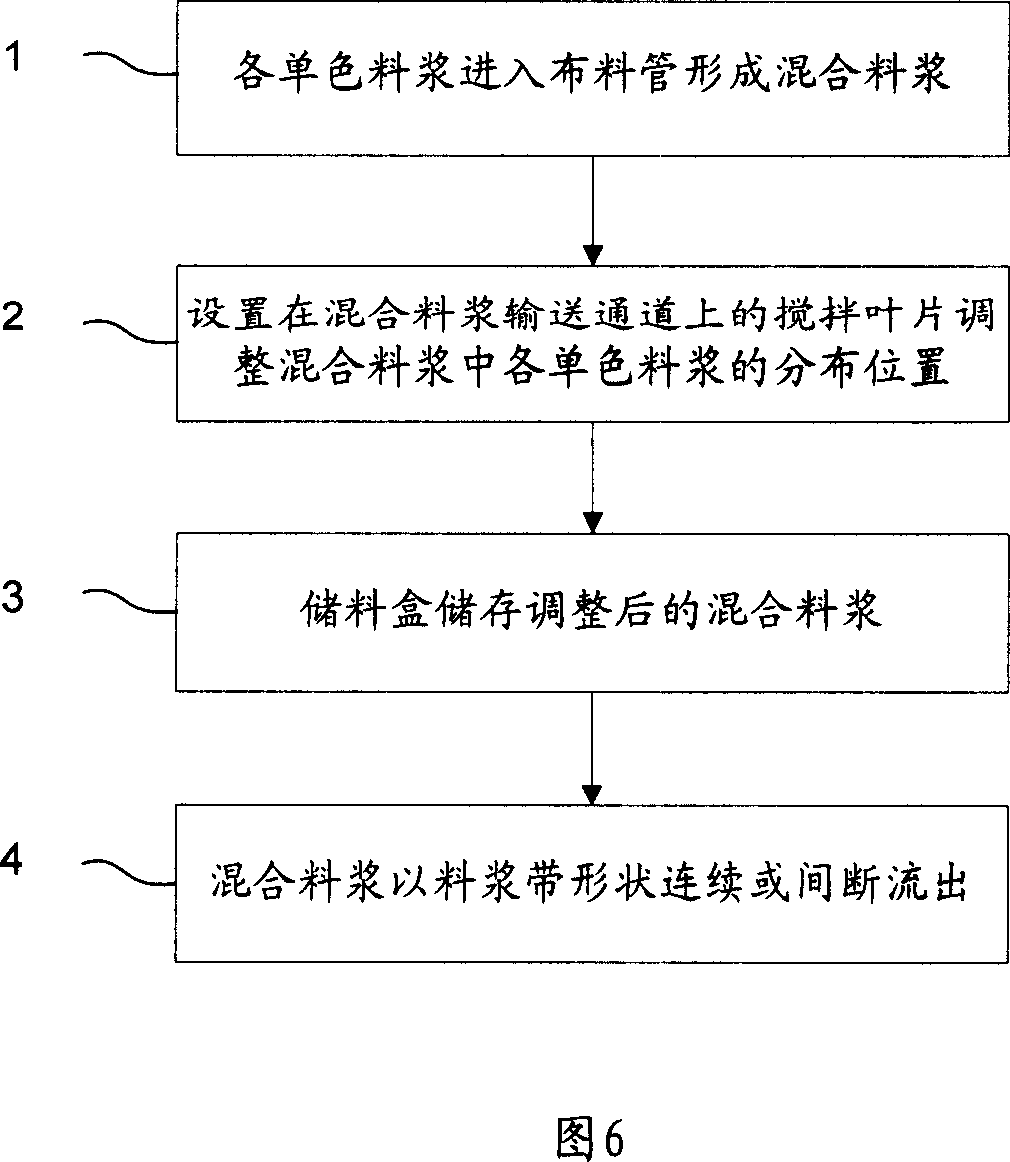
[0034] In this embodiment, the agitator 3 is arranged on the conveying channel of the material distribution pipe 1, the material distribution pipe 1 is connected with the material storage box 2, and the material storage box 2 is provided with a material outlet 21, which is used to turn the agitator The mixed slurry in 3 flows out in the shape of a slurry belt with a certain thickness and width. As shown in Figure 1, the discharge port 21 of the present embodiment is arranged on the bottom of the material storage box 2, and the height of the discharge port 21 can be set as required to control the thickness and width of the slurry belt flowing out, so that the present invention is suitable for various Production of tiles of various specifications. The discharge port 21 can also be provided with a partition for controlling the discharge of the discharge port 21 or stopping the discharge, so as to realize the control of the length of a single slurry belt. Specifically, each monoc...
no. 3 example
[0037] This embodiment is an improvement based on the technical solution of the second embodiment. After the mixed slurry in the storage box 2 is full, the slurry belt starts to flow out from the outlet 21, and the continuously flowing slurry belt enters the subsequent production process. . Specifically, after the slurry belt enters the subsequent production process, it first enters the dryer to dry to reduce the water content of the slurry belt, and the dried slurry belt is cut into individual color chips according to the tile specifications, and the color chips are placed on the cloth The good powder blanks are sent together to the press for pressing, and finally sent to the kiln for calcination to become ceramic tiles. In addition to the tiles produced in this embodiment have the characteristics of very coordinated layout decoration effects in the first and second embodiments, the overall pattern of the tiles is beautiful and naturally non-deformable, and high strength, due...
PUM
 Abstract
Description
Claims
Application Information
 - R&D
- Intellectual Property
- Life Sciences
- Materials
- Tech Scout
- Unparalleled Data Quality
- Higher Quality Content
- 60% Fewer Hallucinations
Browse by: Latest US Patents, China's latest patents, Technical Efficacy Thesaurus, Application Domain, Technology Topic, Popular Technical Reports.
© 2025 PatSnap. All rights reserved.Legal|Privacy policy|Modern Slavery Act Transparency Statement|Sitemap|About US| Contact US: help@patsnap.com


