Auxiliary automatic separator for clutch of hydraulic mixed power city bus

An urban bus and hybrid technology, which is applied in the field of hydraulic hybrid urban bus clutch auxiliary automatic separation device, can solve the problems affecting the energy saving effect of hydraulic hybrid bus and the like

Inactive Publication Date: 2007-08-22
SHANGHAI SHENZHOU VEHICLE RES & DEV
View PDF0 Cites 10 Cited by
  • Summary
  • Abstract
  • Description
  • Claims
  • Application Information

AI Technical Summary

Problems solved by technology

When the engine power and the hydraulic pressure force act on the gearbox at the same time, the engine power and the hydraulic power will interfere with each other and a

Method used


Image

  • Auxiliary automatic separator for clutch of hydraulic mixed power city bus

Examples


Embodiment Construction

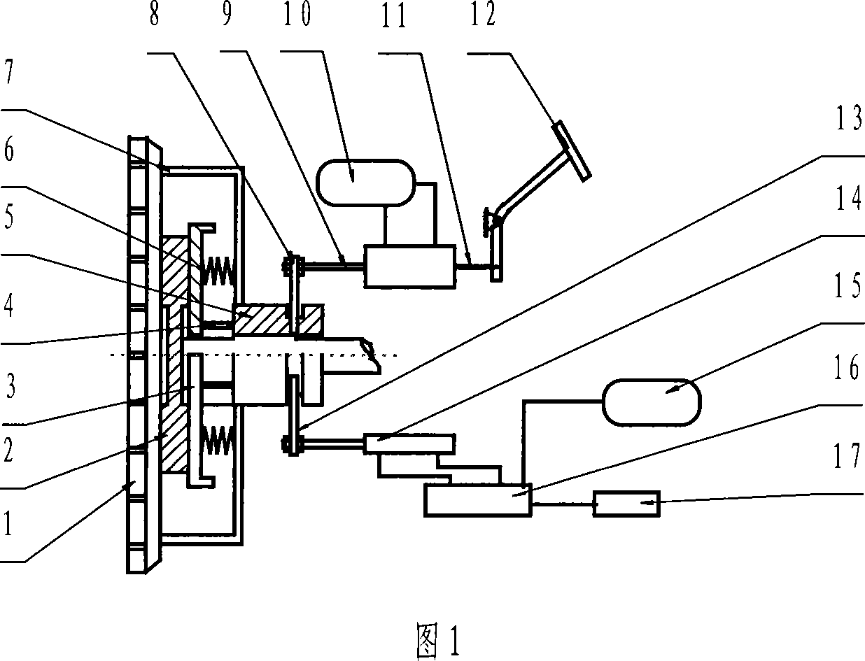
[0010] As shown in Figure 1, the present invention mainly includes: flywheel 1, friction plate 2, pressure plate 3, pressure plate pull rod 4, sliding sleeve 5, pressure plate compression spring 6, clutch bracket 7, hydraulic booster shift fork 8, hydraulic booster pump 9. Hydraulic accumulator 10, clutch pedal connecting rod 11, clutch pedal 12, pneumatic booster shift fork 13, cylinder 14, air storage tank 15, pneumatic control valve 16, CUP controller 17, etc., flywheel 1, friction plate 2, pressure Disc 3, pressure plate pull rod 4, sliding sleeve 5, pressure plate compression spring 6, clutch shift fork 7, hydraulic booster shift fork 8, hydraulic booster pump 9, hydraulic accumulator 10, clutch pedal connecting rod 11, clutch pedal 12 The clutch pedal separation device is formed, and the pneumatic power-assisted shift fork 13, the cylinder 14, the air reservoir 15, the pneumatic control valve 16, and the CPU controller 17 constitute the clutch-assisted automatic separatio...


PUM


Abstract

The present invention relates to one kind of auxiliary automatic separator for clutch of hydraulic mixed power city bus. The present invention can ensure the independent operation of engine power or hydraulic power in mixed power city bus without mutual interference and resistance, and make mixed power city bus possess excellent energy saving effect and excellent operation smoothness.

Description

technical field [0001] The invention relates to a hydraulic hybrid city bus clutch auxiliary automatic separation device, which is used to solve the problem of mutual interference and mutual resistance between the engine power and the hydraulic power in the hydraulic hybrid city bus, thereby ensuring the hydraulic hybrid city bus The bus has greater energy-saving effect and better operation smoothness, and belongs to the field of transportation means. Background technique [0002] The hydraulic hybrid city bus is composed of a hydraulic auxiliary power system composed of hydraulic pump / hydraulic motor, hydraulic accumulator, hydraulic control valve, electronic controller and other components on the bus powered by the engine. The hydraulic hybrid city bus recovers the braking energy of the frequent braking of the bus through the hydraulic power system, and then uses the recovered energy to drive the bus to start and accelerate, thereby achieving energy saving and reducing exh...

Claims


Application Information

Patent Timeline
IPC IPC(8): B60K6/12B60T1/10
CPCY02T10/6208Y02T10/62
Inventor 陈杰刘国庆陶琳阎业翠
Owner SHANGHAI SHENZHOU VEHICLE RES & DEV
Why Eureka
Try Eureka