
Detectable flow electromagnetic valve

A solenoid valve and flow rate technology, applied in the field of automation, can solve the problems that the oil-filled solenoid valve does not realize the fuel flow measurement and control, the oil-filled solenoid valve does not have the flow sensing function, and cannot realize the real-time control of the fuel flow. Easy maintenance and compact structure

Inactive Publication Date: 2007-08-22
SHANGHAI JIAO TONG UNIV
View PDF0 Cites 13 Cited by
  • Summary
  • Abstract
  • Description
  • Claims
  • Application Information

AI Technical Summary

Problems solved by technology

[0003] After searching the literature of the prior art, it was found that Ye Sheng and Hu Jie published a paper entitled "Research on Engine Fuel Consumption Test System Based on Virtual Instrument Technology" in "Journal of Zhejiang University" (Agriculture and Life Science Edition, No. 5 in 2005). "The paper proposed an engine fuel consumption test system, which mainly realizes the measurement and control of fuel flow through the fuel filling solenoid valve and weight sensor. The system has high measurement accuracy and can display instantaneous fuel consumption and average fuel consumption in real time. However, the oil-filled solenoid valve used in this system does not have the flow sensing function itself, and must cooperate with an external weight sensor to realize flow sensing, and the oil-filled solenoid valve cannot realize real-time control of fuel flow. The solenoid valve has not realized the integration of fuel flow measurement and control functions

Method used


Image

  • Detectable flow electromagnetic valve

Examples


Embodiment Construction

[0015] The embodiments of the present invention are described in detail below in conjunction with the accompanying drawings: this embodiment is implemented on the premise of the technical solution of the present invention, and detailed implementation methods and specific operating procedures are provided, but the protection scope of the present invention is not limited to the following the described embodiment.

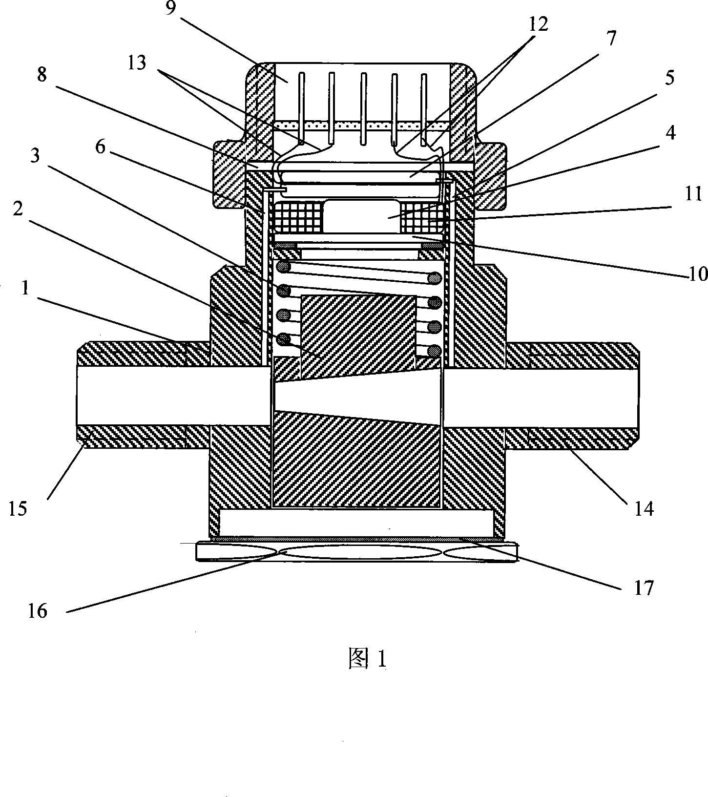
[0016] As shown in Figure 1, this embodiment includes: solenoid valve body 1, valve 2, compression spring 3, electromagnet 4, upstream pressure guiding hole tube 5, downstream pressure guiding hole tube 6, differential pressure sensor 7, plastic soft pressure plate 8 , cable interface 9, solenoid valve body 1 is a shell structure, its interior is hollow, and there are upstream pipe joints 14 and downstream pipe joints 15 on the left and right sides of the outside, and the two ends of the fluid channel are connected with the upstream and downstream pipes through them, t...


PUM


Abstract

The present invention relates to an electromagnetic valve capable of detecting and controlling flow rate. Said electromagnetic valve includes the following several portions: electromagnetic valve self-body, valve lead, compression spring, electromagnet, pressure-guiding hole pipe, differential pressure sensor, plastic soft pressure pipe and electric cable interface. Said invention provides the connection mode of all the above-mentioned portions, and also provides the working principle of said electromagnetic valve and its operation method.

Description

technical field [0001] The invention relates to a control device in the technical field of automation, in particular to a flow rate measureable and controllable electromagnetic valve. Background technique [0002] With the rapid growth of the world's economy and population, the consumption of water resources in the world is also increasing at an alarming rate. How to realize the recycling of water resources and save water has long been a common concern of mankind, which is related to human survival and development. . From the perspective of production process automation, how to save water and control water also deserves special attention. In a word, to realize the control problem of people's water consumption, it must rely on the water flow control device to realize it. Not only that, since ordinary solenoid valves have been widely used in the conduction and closure control of fluid flow, the flow control of different types of fluids in industrial automation must be realiz...

Claims


Application Information

Patent Timeline
Patent Type & Authority Applications(China)
IPC IPC(8): F16K3/02F16K3/314F16K31/06F16K37/00G05D7/06
Inventor 张秀彬张晓芳陈惕存肖健马斌博
Owner SHANGHAI JIAO TONG UNIV
Learn More