Automatic computerized selecting optimized dredging method for cutter suction dredger

A cutter suction dredger and computer technology, which is applied in the field of automatic optimization of cutter suction dredger computer aided dredging, can solve problems such as capacity and level differences affecting dredging output, etc.

Inactive Publication Date: 2007-08-22
中国交通建设集团有限公司
View PDF0 Cites 37 Cited by
  • Summary
  • Abstract
  • Description
  • Claims
  • Application Information

AI Technical Summary

Problems solved by technology

[0004] In the existing cutter suction dredger operating condition monitoring system, only the plane positioning and section system, traverse winch system, reamer motor system, underwater pump system, in-cabin pump system, There is

Method used


Image

  • Automatic computerized selecting optimized dredging method for cutter suction dredger
  • Automatic computerized selecting optimized dredging method for cutter suction dredger
  • Automatic computerized selecting optimized dredging method for cutter suction dredger

Examples


Embodiment Construction

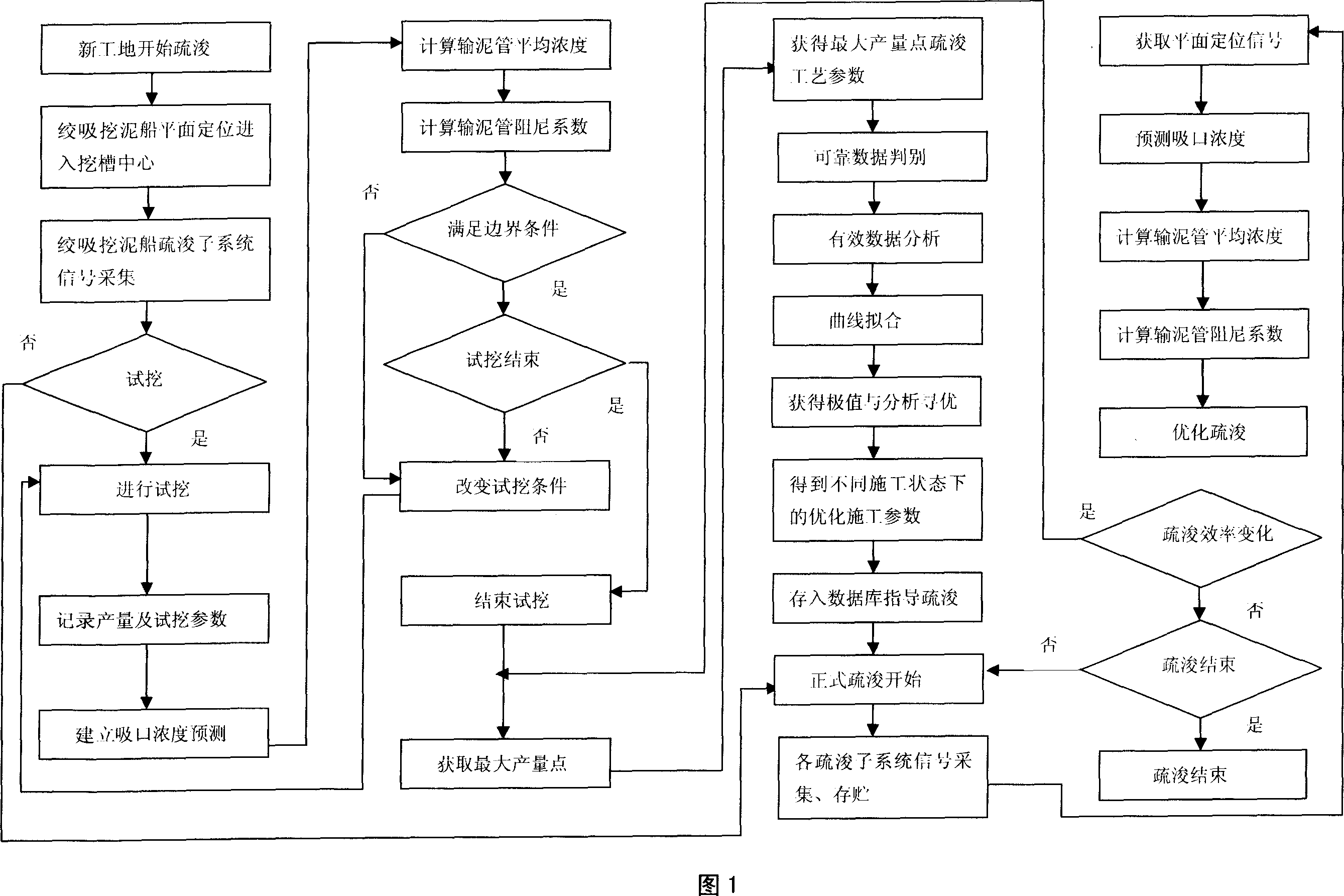
[0069] The method flow of the present invention is shown in Figure 1:

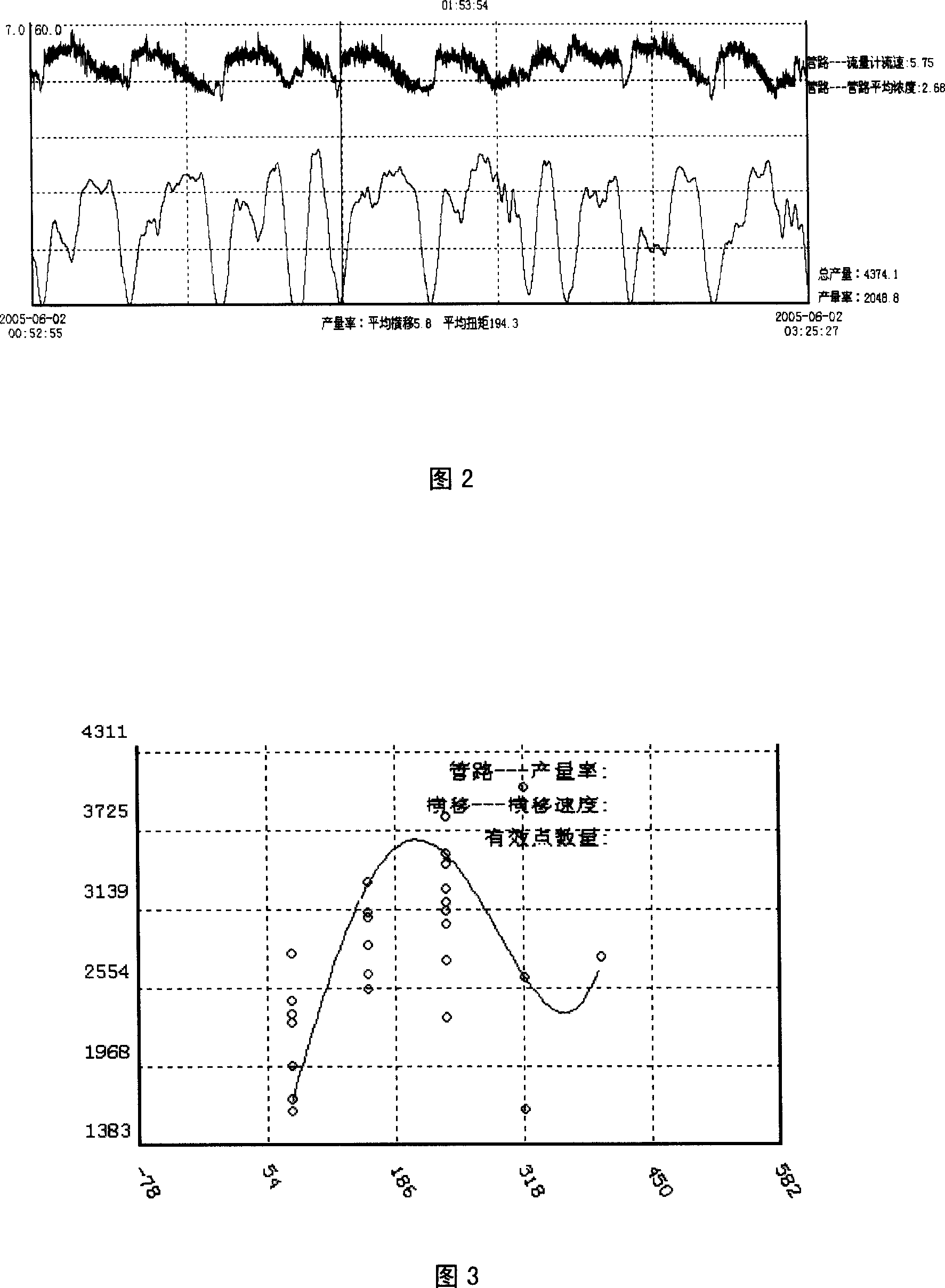
[0070] Before the formal dredging construction, the cutter suction dredger enters the center of the trench, the positioning pile is placed on the center line of the trench through the plane positioning system, and the signals of each dredging subsystem of the cutter suction dredger are collected for trial excavation. Since the trial excavation and dredging process is greatly affected by water flow, wind direction, and inequality and uncertain factors at the bottom of the original riverbed, the raw data continuously collected during the dredging process is a set of oscillating and unstable data (as shown in Figure 2).

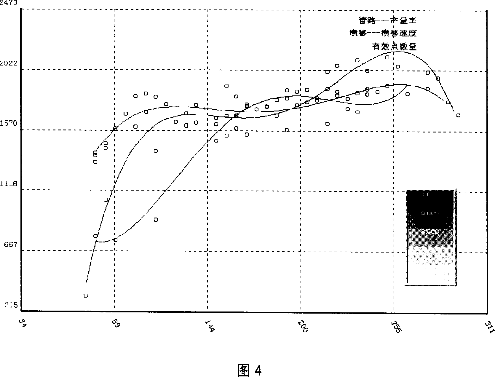
[0071] The system uses mathematical statistical analysis on the oscillation data to obtain true, reliable and smooth results. Set the section for each data that needs to be analyzed. For example, the traverse speed varies from 0m / min to 16m / min. The system divides this 16m / min interval into 40 i...


PUM


Abstract

This invention relates to an automatic optimizing method for assistant dredging up with a computer of a cutter suction dredger including: collecting the dredge up subsystem signals of a cutter suction dredger, registering the output and related trial digging parameter, setting up a forecast model of suction density, computing the mean density, and dampon coefficient for mud transporting tubes and judging if the trial digging parameter and result meet the set border condition, reliable data judgment, effective data analysis, curve fit to get the optimum construction parameter to carry out optimized dredge up.

Description

Technical field [0001] The invention belongs to the technology of channel dredging, and relates to an automatic optimization method for computer-aided dredging of a cutter suction dredger. Background technique [0002] The cutter suction dredger uses the movement of the cutter installed at the front end of the cutter bridge to break the soil. The rotating cutter continuously loosens the sea (river) bottom mud (sand, rocks, etc.) and mixes the mud with water. The mixed muddy water is sucked in through the suction port under the action of atmospheric pressure, pressurized by the mud pump, and transported to the filling area (or designated mud unloading area) by the mud pipe. [0003] Most of the cutter suction dredgers are equipped with positioning steel piles (positioning pile trolleys) and steel pile lifting devices, which are used for positioning the dredger in dredging operations, lateral movement and longitudinal movement of the hull, etc. The left and right anchors and anchor...

Claims


Application Information

Patent Timeline
IPC IPC(8): G06F17/50G06F17/00E02F3/88
Inventor 田俊峰周泉生顾明俞孟蕻刘瑞祥丁友树李阿福李金贵李文义王健李进军马国强唐印吴正松李瑞祥
Owner 中国交通建设集团有限公司
Why Eureka
Try Eureka