
Dispatching device and method in optical communication network

A technology of optical communication network and dispatching device, which is applied in multiplexing system selection device, selection device, multiplexing communication, etc., can solve problems such as optical noise accumulation and conflict, and achieve limited management and avoid Cumulative, avoiding the effect of optical wavelength conflicts

Active Publication Date: 2007-08-22
HUAWEI TECH CO LTD
View PDF0 Cites 5 Cited by
  • Summary
  • Abstract
  • Description
  • Claims
  • Application Information

AI Technical Summary

Problems solved by technology

[0005] Embodiments of the present invention provide a scheduling device and a scheduling method in an optical communication network, which solves the problem of optical noise accumulation, avoids optical wavelength conflicts, and supports multicast and broadcast services

Method used


Image

  • Dispatching device and method in optical communication network
  • Dispatching device and method in optical communication network
  • Dispatching device and method in optical communication network

Examples


Embodiment Construction

[0036] The technical solutions of the present invention will be described in detail below with reference to the accompanying drawings and examples.

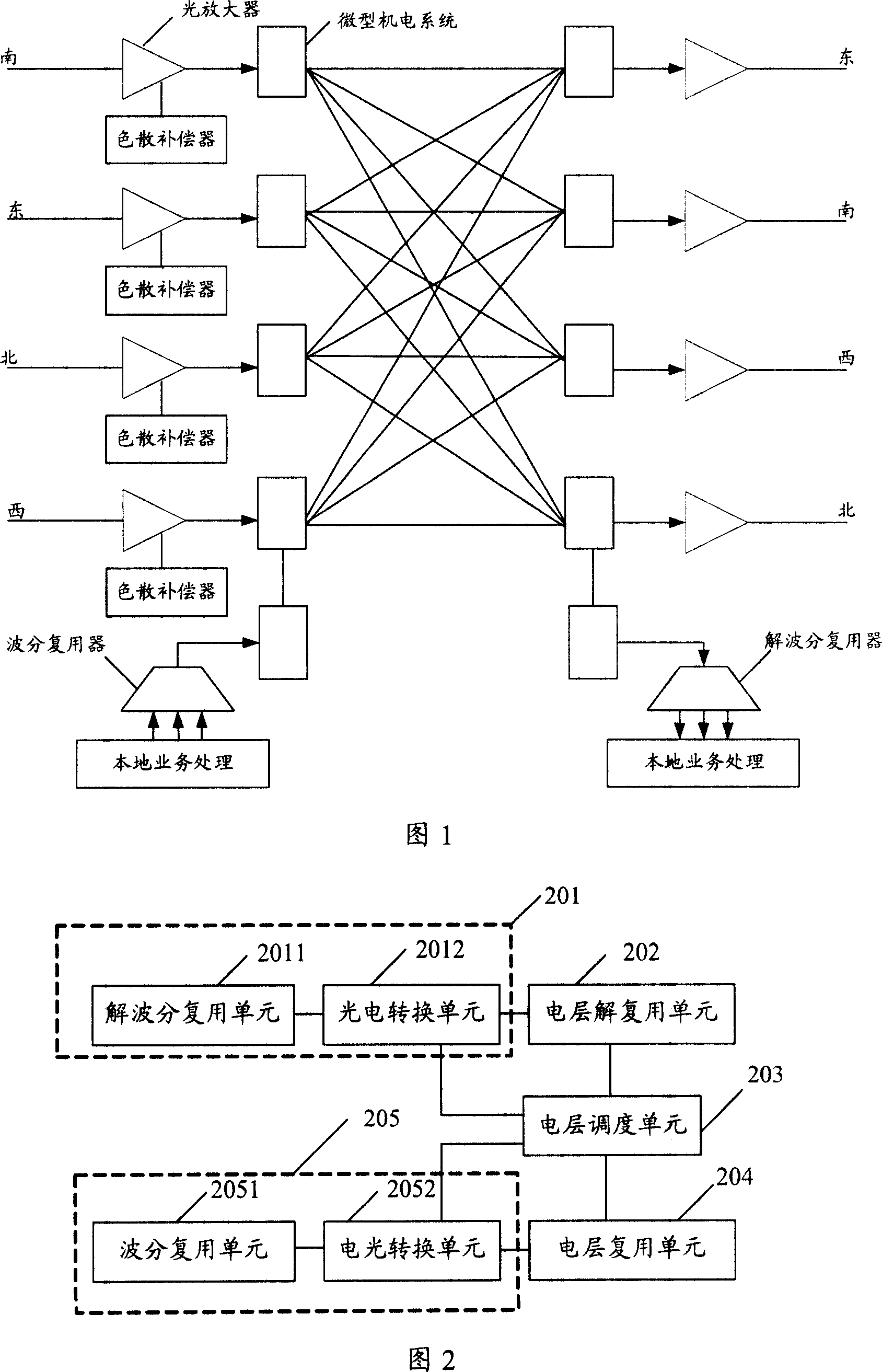
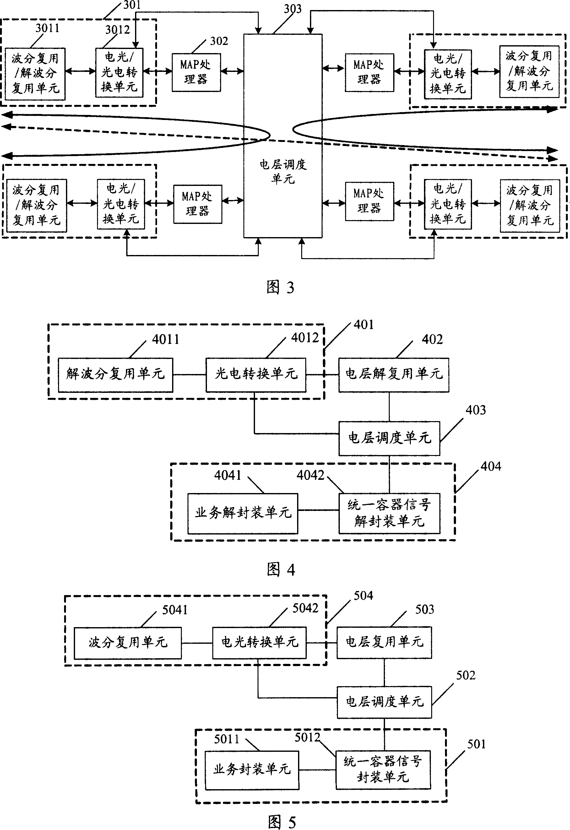
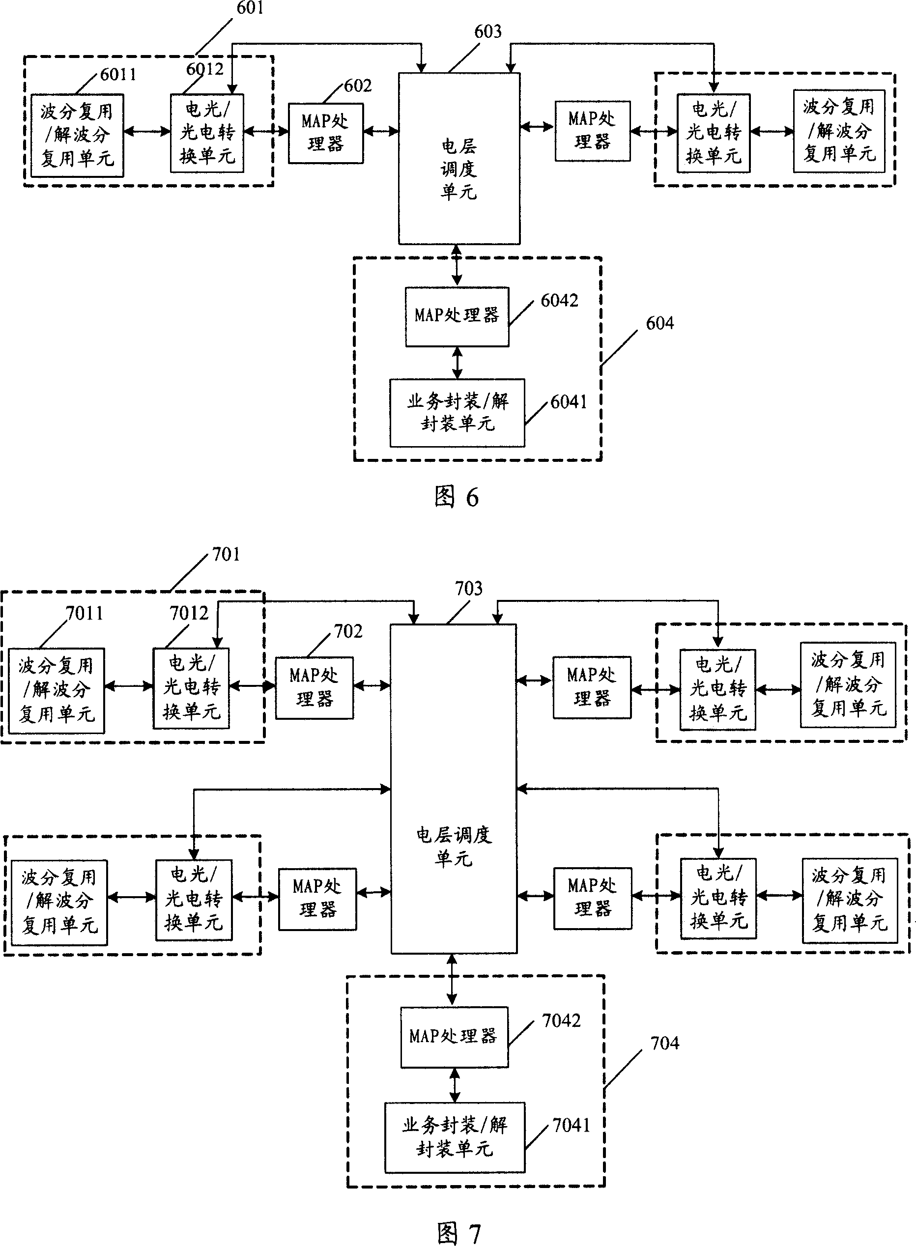
[0037] Referring to FIG. 2 , Embodiment 1 of the present invention provides a scheduling device in an optical communication network, which is used for scheduling optical wavelengths. The device includes: a first optoelectronic integration unit 201, an electrical layer demultiplexing unit 202, and an electrical layer scheduling unit 203, electrical layer multiplexing unit 204, second optoelectronic integration unit 205; wherein, the first optoelectronic integration unit 201 includes: demultiplexing unit 2011, photoelectric conversion unit 2012; the second optoelectronic integration unit 205 includes: electro-optical conversion unit 2052, a wavelength division multiplexing unit 2051;

[0038] The multi-wavelength optical signal is decomposed into a plurality of single-wavelength optical signals through the demultiplexing unit 2011,...


PUM


Abstract

A dispatch device in optical communication network is prepared as forming photoelectric integrated unit by wavelength division multiplexing / de-multiplexing component for decomposing multi-wavelength optical signal to be multiple single wavelength optical signal and photoelectric / electro-optic conversion component for converting single wavelength optical signal to be single wavelength electric signal, and using electric layer dispatching unit to dispatch electric signal of single wavelength.

Description

technical field [0001] The invention relates to scheduling technology in communication, in particular to a scheduling device and a scheduling method in an optical communication network. Background technique [0002] With the rapid growth of packet services, future communication network design should focus on optimizing support for packets, especially IP services. Therefore, it is very important to improve service scheduling capabilities and achieve high-efficiency service transmission. At present, the scheduling methods mainly include: wavelength-level electrical crossover or optical crossover, such as reconfiguration optical add / drop multiplexing (Reconfiguration Optical Add / Drop Multiplexing, ROADM), which can selectively transmit up and down local services and certain wavelengths, and Transmission of other wavelengths is not affected. [0003] The existing ROADM is ROADM based on wavelength selective switch (Wavelength Select Switch, WSS). Its structural block diagram is...

Claims


Application Information

Patent Timeline
Patent Type & Authority Applications(China)
IPC IPC(8): H04J14/02H04B10/12
CPCH04Q11/0005H04J14/0212H04J14/0213H04J14/0217H04Q11/0071H04Q2011/0016H04Q2011/0039H04Q2011/005
Inventor 黄志勇王步云
Owner HUAWEI TECH CO LTD
Learn More