
Permanent magnet bias-magnetic axial mixed magnetic bearing

An axial hybrid magnetic bearing technology, applied in the direction of shafts and bearings, bearings, mechanical equipment, etc., can solve the problems of large volume, unreasonable design, and rareness of axial hybrid magnetic bearings, achieving simple structure and reducing Moment of inertia, effect of reducing ampere-turns

Inactive Publication Date: 2007-08-29
JIANGSU UNIV
View PDF1 Cites 32 Cited by
  • Summary
  • Abstract
  • Description
  • Claims
  • Application Information

AI Technical Summary

Problems solved by technology

[0002] Since the rapid development of magnetic bearing technology in the 1970s, the technology of radial hybrid magnetic bearings has been relatively mature, while the technology of single axial hybrid magnetic bearings is still rare, especially in the design of mechanical structures and magnetic circuit structures. In terms of design, the design is not very reasonable, and the disadvantages of large volume, heavy weight and high power consumption of axial hybrid magnetic bearings are common.

Method used


Image

  • Permanent magnet bias-magnetic axial mixed magnetic bearing
  • Permanent magnet bias-magnetic axial mixed magnetic bearing

Examples


Embodiment Construction

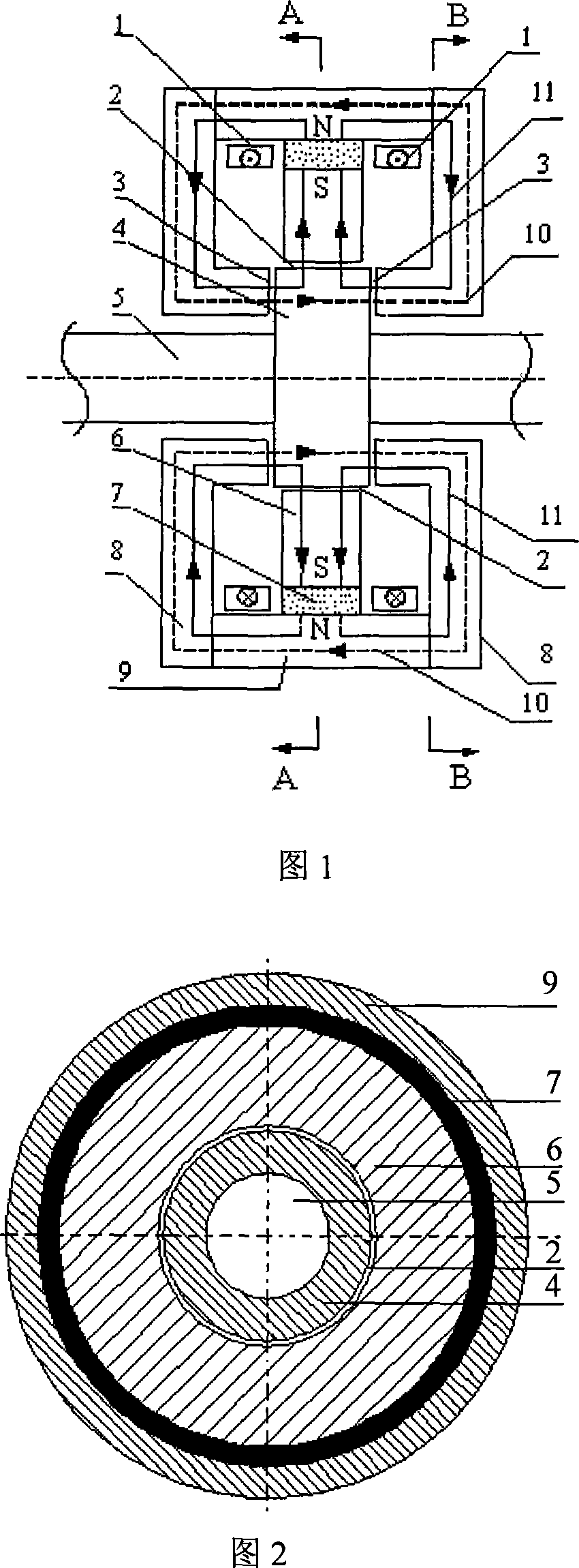
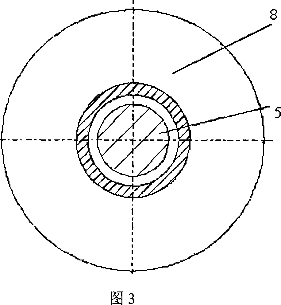
[0013] As shown in Figures 1 and 2, it is the permanent magnetic bias axial hybrid magnetic bearing of the present invention, which is the basic structure of the present invention, and it consists of axial control coil (1), rotor (4), rotating shaft (5), It consists of a radial stator (6), an annular permanent magnet (7), an axial stator disk (8), and an axial stator cylinder (9). Two axial control coils (1) are connected in series and placed between two axial stator discs (8), and placed on the inner side next to the axial stator cylinder (9) to generate control magnetic flux; the rotor ( 4) It is made of laminated circular silicon steel sheets, which are set on the rotating shaft (5); the radial stator (6) is made of laminated silicon steel sheets, and placed in the axial stator cylinder with the circular permanent magnet (7) (9) inside, forming a radial air gap (2) with the rotor (4); two axial air gaps (3) are formed between the two axial stator disks (8) and the rotor (4)...


PUM


Abstract

The invention is a permanent magnet biasing axial mixed magnetic bearing, relating to the technical field of electromechanical engineering, comprising axial control coils, rotor, rotating shaft, stator, permanent magnet, axial stator discs, and axial stator cylinder, where two axial control coils are connected in series and respectively arranged between two axial stator discs and arranged inside and close to the axial stator cylinder; the rotor is jacketed on the rotating shaft; radial stator and permanent are arranged inside the axial stator cylinder and a radial gap is formed between the radial stator and the rotor; two axial gaps are formed between two axial stator discs and the rotor; the two axial stator discs, axial stator cylinder, two axial gaps and rotor compose a complete control flux circuit; the permanent magnet is inserted between the axial stator cylinder and the radial rotor, and forms permanent magnet biasing magnetic circuit path together with the radial gap and the rotor through the two axial gaps, respectively. And the invention need not install a large axial suction disc on the rotating shaft, largely reducing moment of inertia of the rotor, and the structure is simple, and it is easy to install.

Description

technical field [0001] The invention relates to the technical field of electromechanical engineering, in particular to a permanent magnetic bias axial hybrid magnetic bearing, which is suitable for rotating parts in mechanical equipment such as 5-degree-of-freedom magnetic bearing systems, axial positioning of bearingless motors, and high-speed flywheel energy storage systems. Axial non-contact suspension support. Background technique [0002] Since the rapid development of magnetic bearing technology in the 1970s, the technology of radial hybrid magnetic bearings has been relatively mature, while the technology of single axial hybrid magnetic bearings is still rare, especially in the design of mechanical structures and magnetic circuit structures. On the other hand, the design is not very reasonable, and the axial hybrid magnetic bearings generally have the disadvantages of large volume, heavy weight and large power consumption. [0003] In order to reduce the axial and ra...

Claims


Application Information

Patent Timeline
IPC IPC(8): F16C32/04
CPCF16C32/0476F16C32/0465
Inventor 朱熀秋贾红云谢志意孙玉坤
Owner JIANGSU UNIV
Learn More