
Reflexible color LCD and its manufacturing method

A technology of a liquid crystal display device and a manufacturing method, which is applied in the direction of manufacturing tools, optics, instruments, etc., can solve problems such as blurred display, high cost, and damage to the uniformity of liquid crystal display, and achieve the effect of reducing parallax and maintaining uniformity

Inactive Publication Date: 2007-08-29
NANOX
View PDF1 Cites 6 Cited by
  • Summary
  • Abstract
  • Description
  • Claims
  • Application Information

AI Technical Summary

Problems solved by technology

[0004] However, when a glass substrate is used as the substrate 103, 104, 107, 108, 111, 112 of the reflective LCD 105, 109, 113, as shown in FIG. The distance between the layer 102 and the blue reflective liquid crystal layer 110 (the distance A between the reflective liquid crystal layers) becomes longer, and parallax (angle dependence of visibility) B occurs based on the distance A between the reflective liquid crystal layers. The display becomes blurred and high-definition display cannot be realized
Here, it is conceivable to use a glass substrate with a thinner thickness t, but a glass substrate with a thinner thickness t is more expensive, and the manufacturing process of the color display cholesteric liquid crystal display 100 does not support the case of a thinner glass substrate. In order to adapt the manufacturing process to a thin glass substrate, a huge amount of equipment costs is required, and the yield may decrease and the cost may increase.
[0005] In addition, in the case of using a flexible substrate as the substrate 103, 104, 107, 108, 111, 112 of the reflective LCD 105, 109, 113, although it is easy to make the flexible substrate thinner, the flexibility of the transparent conductive film (ITO film) is formed. The substrate is expensive, and since the flexible substrate has high flexibility, it is difficult to uniformly form the liquid crystal cell (cell) gap into which the liquid crystal is injected, which sometimes impairs the uniformity of the liquid crystal display

Method used


Image

  • Reflexible color LCD and its manufacturing method
  • Reflexible color LCD and its manufacturing method
  • Reflexible color LCD and its manufacturing method

Examples


Embodiment Construction

[0040] Hereinafter, a reflection type color liquid crystal display device according to an embodiment of the present invention will be described with reference to the drawings.

[0041] FIG. 1 is a cross-sectional view schematically showing the configuration of a reflective color liquid crystal display device according to an embodiment of the present invention.

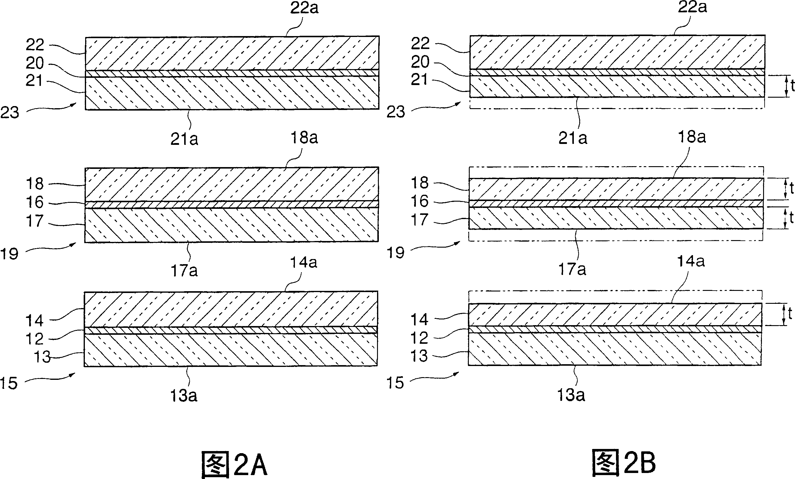
[0042] In FIG. 1, a color display cholesteric liquid crystal display 10 as a reflective color liquid crystal display device is provided with: a black light absorbing layer 11; A red reflective liquid crystal layer 12 showing a red reflective color is formed between them; a green reflective LCD 19 laminated on the red reflective LCD 15 has a green reflective liquid crystal layer 16 showing a green reflective color formed between the glass substrates 17 and 18 and a blue reflective LCD 23 laminated on the green reflective LCD 19, in which a blue reflective liquid crystal layer 20 showing a blue reflective color is formed...


PUM

PropertyMeasurementUnit
thicknessaaaaaaaaaa

Abstract

The present invention provides a reflection type color liquid crystal display device which can maintain the homogeneity of liquid crystal display and can reduce the parallax and its manufacturing method. The reflection type color liquid crystal display device has a light absorbing layer (11) and a red reflect LCD (15), a green reflect LCD (19) and a blue reflect LCD (23) cascaded on the light absorbing layer (11) in sequence. These reflect liquid crystal displays (15, 19 and 23) have plural glass base plates (13 and 14, 17 and 18, 21 and 22) and liquid crystal layers (12, 16 and 20) formed among the plural glass base plates (13 and 14, 17 and 18, 21 and 22). At least two surfaces of the plural glass base plate surfaces between the first liquid crystal layer (12) disposed nearest to the light absorbing layer (11) and the second liquid crystal layer (20) disposed farthest to the light absorbing layer (11) are grinded; and the maximum value of the parallax B (mm) represented by the follow formula is lower than 0.51 mm. B=A x tan(arcsin(sinTheta / n) x cosTheta); Theta: view angle; A: distance (mm) between reflect liquid crystal layer; n: the refractivity of the grinded glass base plate.

Description

technical field [0001] The present invention relates to a reflective color liquid crystal display device and a manufacturing method thereof, in particular to a color display cholesteric liquid crystal display formed by stacking reflective liquid crystal displays (reflective LCDs) and a manufacturing method thereof. Background technique [0002] A color display cholesteric liquid crystal display is constructed by laminating reflective liquid crystal displays (reflective LCD) that select and reflect a predetermined wavelength. For example, as shown in FIG. 9 , a color display cholesteric liquid crystal display 100 is equipped with: a black light absorbing layer 101; The red reflective liquid crystal layer 102 of the reflective color; the green reflective LCD 109 laminated on the red reflective LCD 105, and the green reflective liquid crystal layer 106 showing the green reflective color is formed between the substrates 107 and 108; and the green reflective LCD 109 laminated on ...

Claims


Application Information

Patent Timeline
Patent Type & Authority Applications(China)
IPC IPC(8): G02F1/1333B24B9/02B24B9/08B24B9/10
Inventor 鸟原秀胜高野敦史
Owner NANOX
Learn More