Power-fail protection method based on two continuous logical blocks for non-volatile memory

A non-volatile, power-down protection technology, applied in the protection of storage content to prevent loss, redundancy in operation for data error detection, response error generation, etc. , hidden dangers and other problems, to achieve the effect of improving reliability and safety, ensuring consistency and integrity, and improving service life

Active Publication Date: 2007-08-29
FEITIAN TECHNOLOGIES
View PDF0 Cites 24 Cited by
  • Summary
  • Abstract
  • Description
  • Claims
  • Application Information

AI Technical Summary

Problems solved by technology

[0008] 4) The service life of Flash memory is limited
The hard protection circuit in the prior art is cumbersome, the circuit design is complicated, and it is not easy to integrate
And the existing soft protection method in the prior art: read the corresponding file information according to the file header information, then change the data that needs to be modified in the data body into the required data content in the middle of the memory, modify the file header information, and finally find again A storage area that has not been used or has not been used after erasing, writes the modified content in the memory to the corresponding po

Method used

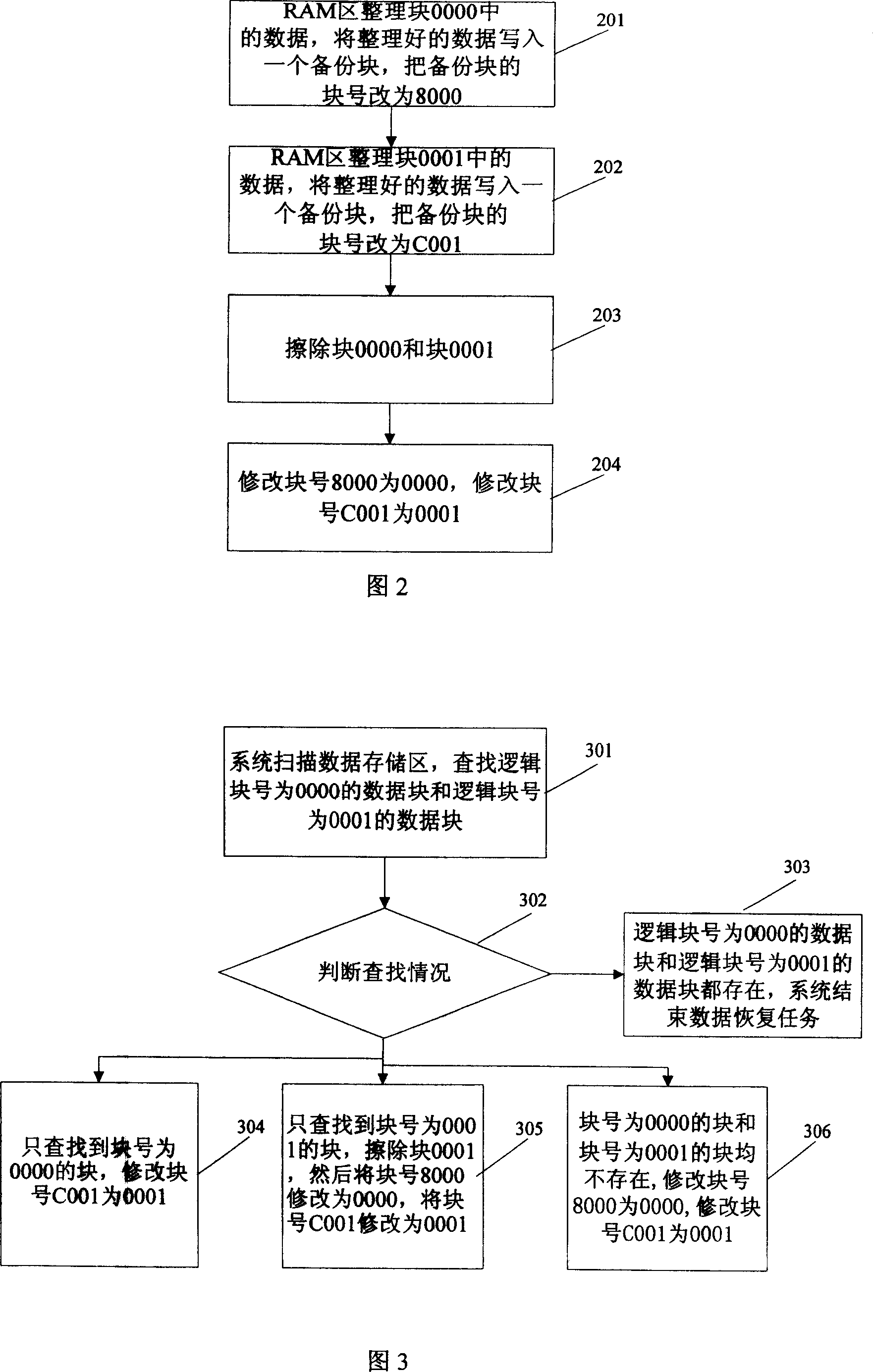

Image

  • Power-fail protection method based on two continuous logical blocks for non-volatile memory
  • Power-fail protection method based on two continuous logical blocks for non-volatile memory
  • Power-fail protection method based on two continuous logical blocks for non-volatile memory

Examples


Embodiment 1

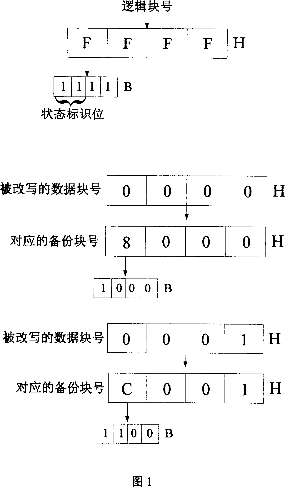
[0042] In this embodiment, two data blocks with consecutive logical addresses are taken as an example to specifically introduce the process of data protection and recovery after power failure. In this embodiment, the logical block number is represented by two bytes, that is, four hexadecimal numbers, and the user's PIN code is stored in the rewritten data block. In this embodiment, select two data blocks that have been erased in the Flash storage area as the backup block, and set the high two bits of the logical block number of the backup block as the status flag, and represent the backup block and the backup block by rewriting the status flag. Correspondence of the data blocks to be rewritten.

[0043] As shown in Figure 1, in the present embodiment, the block number of the data block that is rewritten is 0000 and 0001, utilizes the characteristic that Flash stores simultaneously, promptly when a Flash memory area is in clean state (was erased, But there is no write operatio...

Embodiment 2

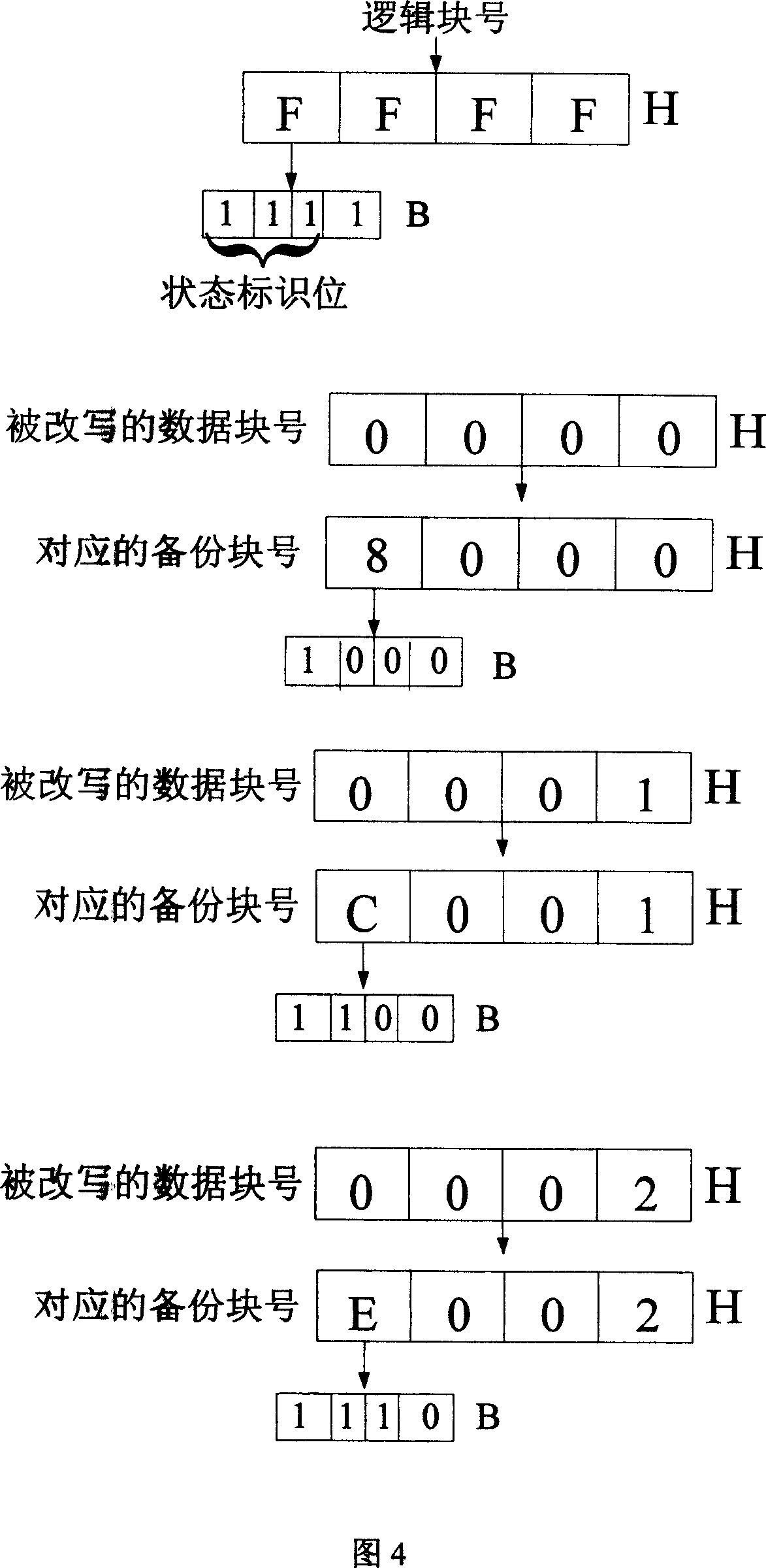
[0059] In this embodiment, three data blocks with consecutive logical addresses are taken as an example to specifically introduce the process of data protection and recovery after power failure. In this embodiment, the logical block number is represented by two bytes, and the key data of the user is stored in the rewritten data block. In this embodiment, the three data blocks that have been erased in the Flash storage area are also selected as the backup block, and the high two bits of the logical block number of the backup block are set as the status flag, and the backup block is represented by rewriting the status flag The corresponding relationship with the rewritten data block.

[0060] As shown in Figure 4, in this embodiment, the block numbers of the rewritten data blocks are 0000, 0001, 0002, the storage block with the logical block number FFFF is used as the backup block, and the upper three bits of the logical block number are set to Status flag. When the upper thre...


PUM


Abstract

The invention relates to a data power-off protection method, especially relating to a power-off protection method based on two continuous logic blocks in a nonvolatile memory, adding one or more backup blocks in a memory area and on the basis of the original logic block number, adding state flag bit of logic block, and comprising trans-block data power-off safety rewrite course and after-power-on data recovery course. By adding backup blocks, the invention assures the data is uneasy to lose at power off while rewriting multiple data blocks, largely improving data storage reliability and safety, and effectively avoiding frequently erasing some erase block so as to prolong Flash memory service life.

Description

technical field [0001] The invention relates to a data power-down protection method, in particular to a power-down protection method based on two continuous logic blocks in a nonvolatile memory. Background technique [0002] With the rapid development and wide application of storage devices, there is a great demand for a storage device that can realize multiple programming, large capacity, fast, convenient and simple reading, writing and erasing, and has few peripheral devices and low price. The flash memory (Flash Memory) storage medium emerges at the historic moment under this demand. Flash memory is a memory based on semiconductors. It has the functions of retaining internal information after the system is powered off, and online erasing. It is a new type of memory that replaces EEPROM storage media. Because its read and write speed is faster than EEPROM, and the cost is lower under the same capacity, so the memory card composed of flash memory (Flash memory) is graduall...

Claims


Application Information

Patent Timeline
IPC IPC(8): G06F12/16G06F11/14
Inventor 陆舟于华章
Owner FEITIAN TECHNOLOGIES
Why Eureka
Try Eureka