Automatic lifter of carpet tufting machine needle bar

A technology of automatic lifting device and tufting machine, applied in the field of carpet tufting machines

Inactive Publication Date: 2010-09-29
王龙耀
View PDF2 Cites 0 Cited by
  • Summary
  • Abstract
  • Description
  • Claims
  • Application Information

AI Technical Summary

Problems solved by technology

[0003] Aiming at the defects existing in the current carpet tufting machines, the present invention designs a machine that can quickly and automatically tuft up and down when weaving tufting, and can automatically lift the needle bar when the tufting and weaving are stopped, so as to improve production efficiency. Reduce labor intensity and protect labor resources while improving efficiency and product quality

Method used


Image

  • Automatic lifter of carpet tufting machine needle bar
  • Automatic lifter of carpet tufting machine needle bar
  • Automatic lifter of carpet tufting machine needle bar

Examples


Embodiment Construction

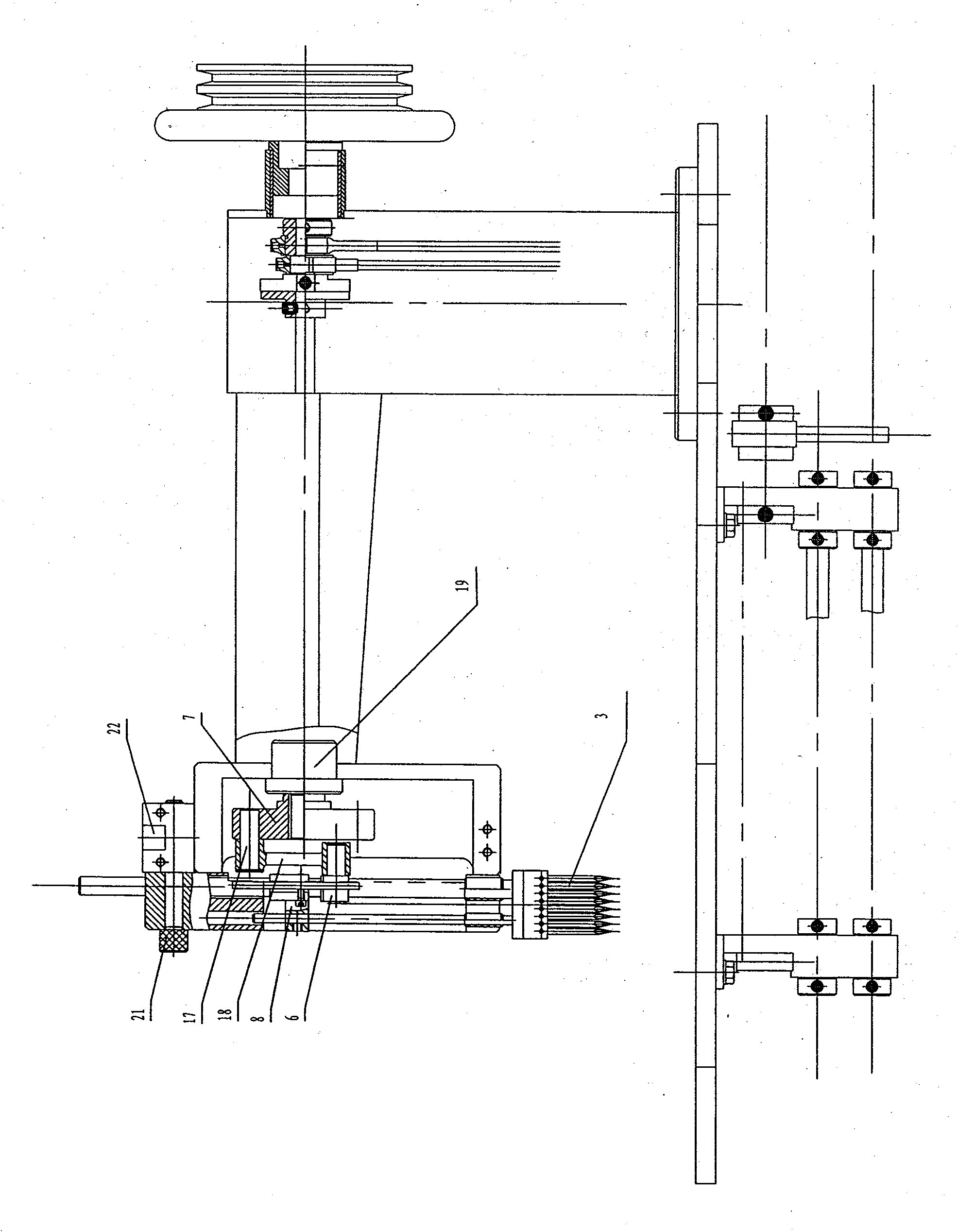
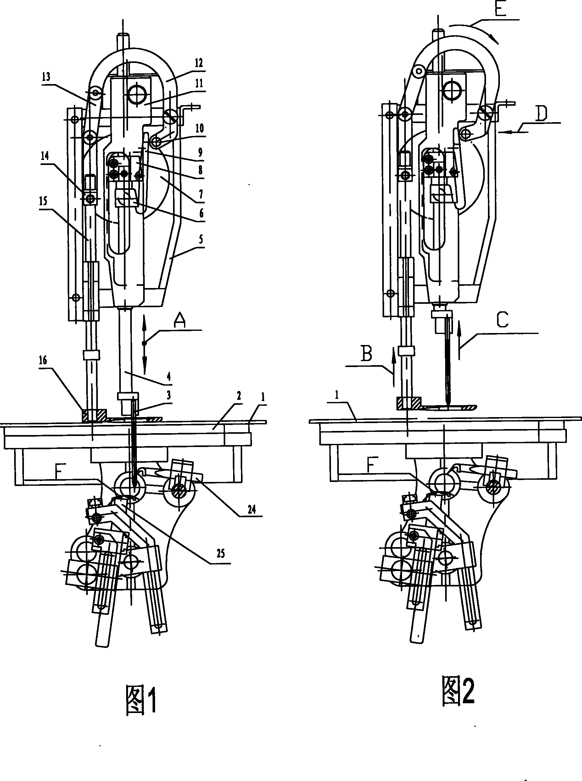
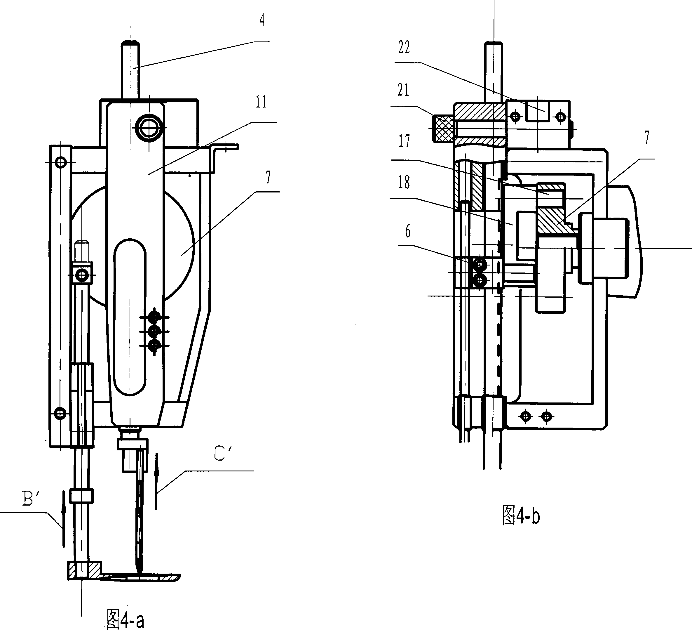
[0011] Carpet tufting head structure see figure 1 , figure 2 and image 3 As shown, it includes a machine head 5, a needle bar 4, a machine needle 3 and a platen 2, the carpet 1 is on the surface of the platen 2, and the lower part of the platen is a hook knife 24 and a straight knife 25. The inner side of the machine head 5 is provided with a transmission flywheel 7 driven by an electric motor 19, and an eccentric pin 17 is arranged on the transmission flywheel 7. One end of the eccentric pin 17 is embedded in the transmission flywheel 7, and the other end is vertically connected and fastened with a connecting rod 18. The connecting rod 18 The other end is fixedly connected with a connecting block 6 . The eccentric pin 17 on the transmission flywheel is parallel to the central axis of the transmission flywheel, and the eccentric pin 17 and the connecting rod 18 are vertically connected to form a crank connecting rod structure. A needle bar fixing block 8 is arranged above...


PUM


Abstract

An automatic lifter for carpet tufting machine needle bar consists of flywheel, link on eccentric pin, link block connected with another end of link, needle bar connected with link block vertically, pendulum driven by link block, needle bar fixing block arranged on top of link block, twisted-coil cant hook coupled below link block, whose middle is fixed with needle bar fixing block, transmission bent handle arranged on top of pendulum, one end contacts with upper end of twisted-coil cant hook, another end is fixed connected with medium link block and pressure bar by Connecting board, pressurebar lifter is made up of twisted-coil cant hook coupled below link block and transmission bent handle controlled by pressure bar; needle bar stops at summit instantly while twisted-coil cant hook is automatically uncoupled. It's fast, accurate and efficient, has better quality and less consumption.

Description

technical field [0001] The invention relates to a carpet tufting machine, and an automatic lifting device for a loom needle bar of the carpet tufting machine. Background technique [0002] At present, the carpet tufting machine used in China, whether it is imported from abroad or domestically designed and manufactured, the needle bar in the machine head is driven by the eccentric pin on the transmission flywheel to move up and down to perform tufting action, which is tufting work. When the presser foot plate is pressed down, pressing the woven block tightly, the needle bar of the tufting machine moves up and down continuously, and performs continuous tufting action. When the loom completes one or one pattern, the thread must be cut or moved. When the cloth block is embroidered, the operator should step on the clutch to stop the machine from working. At the same time, the hand wheel must be shaken with the right hand, and the needle bar can be lifted up to the top dead center...

Claims


Application Information

Patent Timeline
Patent Type & Authority Patents(China)
IPC IPC(8): D05C15/08
Inventor 王龙耀
Owner 王龙耀
Why Eureka
Try Eureka