Valve core of ball valve

A spool and ball valve technology, applied in the field of ball valve spools, can solve the problems of poor processing technology, high cost, weak and unstable combination of wear-resistant and corrosion-resistant layer and ball layer

Inactive Publication Date: 2007-09-12
林振龄
View PDF0 Cites 2 Cited by
  • Summary
  • Abstract
  • Description
  • Claims
  • Application Information

AI Technical Summary

Problems solved by technology

[0002] For existing industrial ball valve cores with wear-resistant and corrosion-resistant requirements, if the overall material is made of wear-resistant metal, the cost will be too high and the processing tech...

Method used


Image

  • Valve core of ball valve
  • Valve core of ball valve
  • Valve core of ball valve

Examples


Embodiment Construction

[0013] Below in conjunction with accompanying drawing and embodiment the present invention is described in further detail:

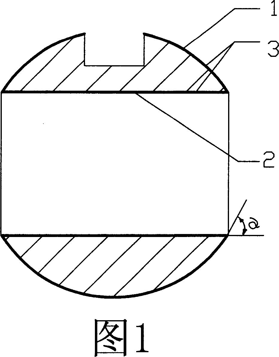
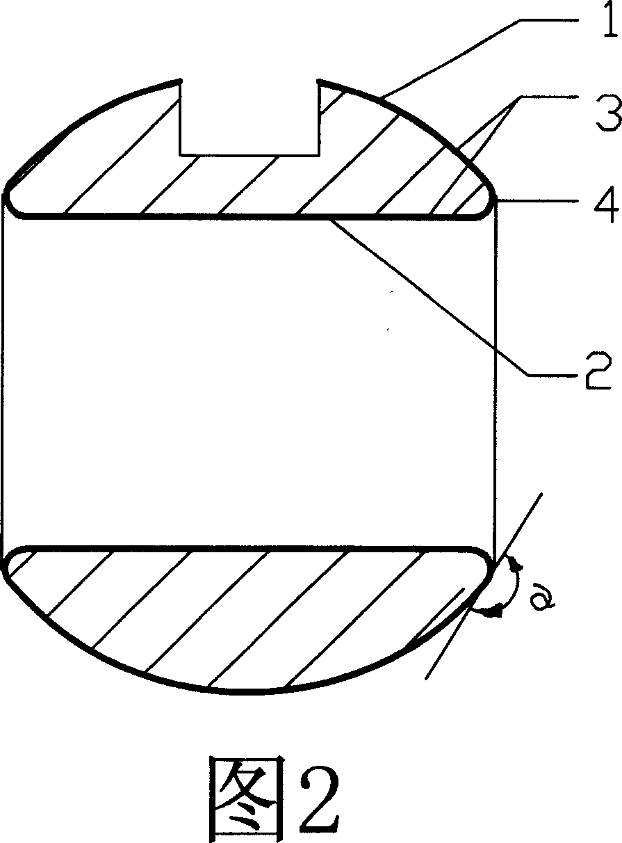
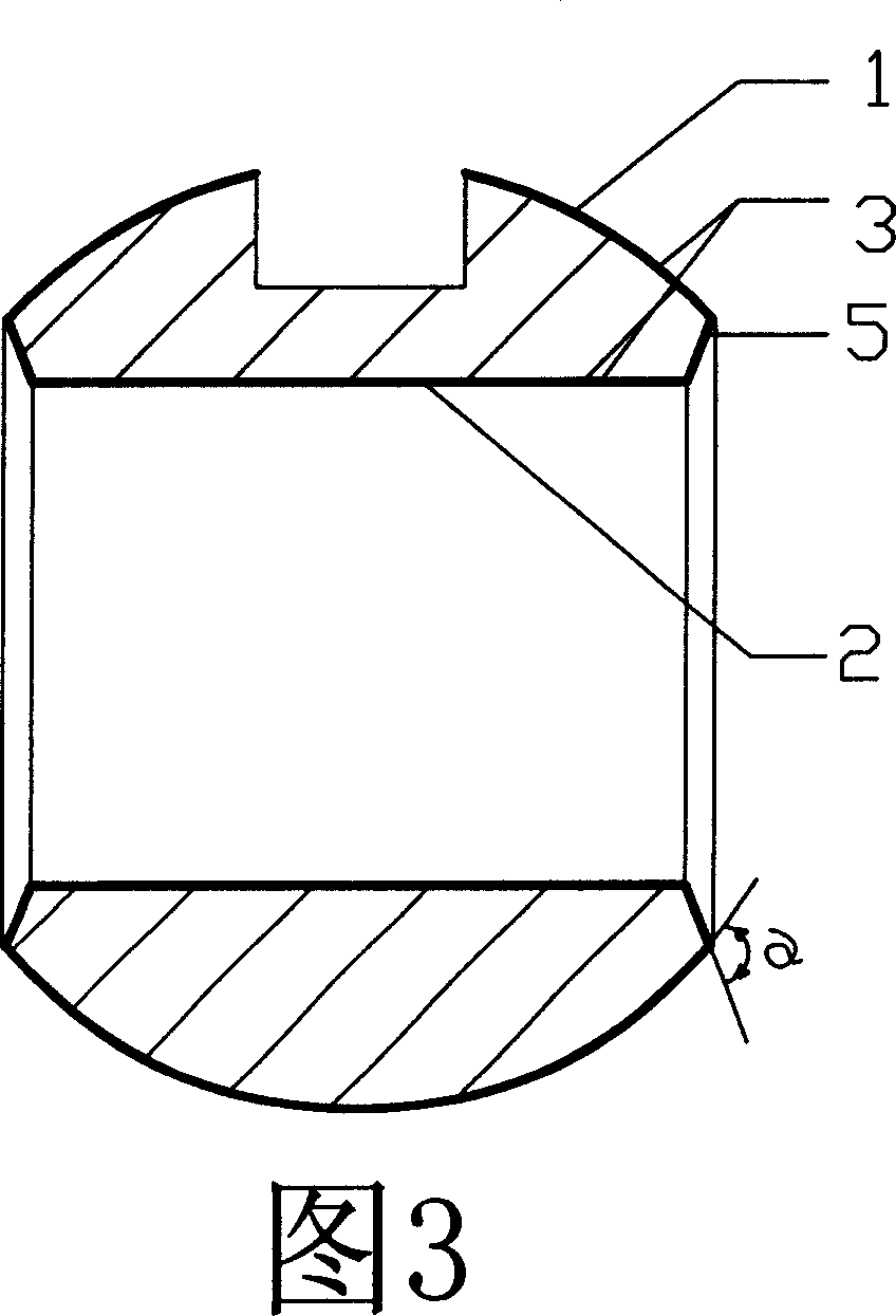
[0014] Among them: 1. The outer spherical surface; 2. The inner cylindrical surface of the through hole; 3. The chromium oxide coating; 4. The transitional arc surface; 5. The transitional conical surface; The angle between the faces at the junction of the two.

[0015] As shown in Figure 1, it is a valve core that does not adopt a transition surface structure. The outer spherical surface 1 of the sphere and the inner cylindrical surface 2 of the through hole are covered with a chromium oxide coating 3, but the outer spherical surface that is stressed is the same as the adjacent The angle α between the non-stressed surfaces is an acute angle, which makes the strength of the junction between the stressed surface and the adjacent non-stressed surface relatively poor, which will affect the stability of the combination of the chromium oxide coating and the s...


PUM


Abstract

The invention offers a kind of ball valve spool which includes external sphere (1) and interlock pore internal straight face (2) and the chrome oxide coat (3) covers on the external sphere (1) with non-rust steel spool and the interlock pore internal straight face (2). There sets up a transitional face at the conjoining location of the external sphere (1) with non-rust steel spool and the interlock pore internal straight face (2) and the included angle of the transitional face and the external sphere (1) at the conjoining location and the transition also covers the chrome oxide coat (3). It is a kind of ball valve spool with low cost, long life, credibility use and wearing and corrosion resistance.

Description

technical field [0001] The invention relates to a ball valve spool, in particular to an industrial ball valve spool with wear-resistant and corrosion-resistant properties. Background technique [0002] For existing industrial ball valve cores with wear-resistant and corrosion-resistant requirements, if the overall material is made of wear-resistant metal, the cost will be too high and the processing technology will be poor. Some valve cores use fluorine-lined technology, but there are also wear-resistant and corrosion-resistant layers. The combination with the sphere layer is not firm and unstable technical defect. Contents of the invention [0003] The object of the present invention is to provide a ball valve spool with low cost, long service life, reliable use, wear resistance and corrosion resistance. [0004] In order to achieve the above object, the technical solution of the present invention is as follows: the outer spherical surface of the stainless steel sphere a...

Claims


Application Information

Patent Timeline
IPC IPC(8): F16K5/06
Inventor 林振龄
Owner 林振龄
Why Eureka
Try Eureka