Method and device of light splitting, image-forming and synchronous phase-shifting in optical interferometry.

A technology of optical interference and synchronous phase shifting, which is applied in measurement devices, optical devices, optical radiation measurement, etc., can solve the problems of high manufacturing process requirements and high cost, and achieve the effects of simple measurement process, convenient purchase and simple method

Inactive Publication Date: 2007-09-12
NANJING NORMAL UNIVERSITY
View PDF0 Cites 24 Cited by
  • Summary
  • Abstract
  • Description
  • Claims
  • Application Information

AI Technical Summary

Problems solved by technology

However, due to the use of holographic gratings for light splitting, in order not to appear unnecessary diffracted light and not to change the wavefront of incident light, the requirements for the grating manufacturing process are relatively high, so the overall cost of this type of interferometer is relatively high

Method used


Image

  • Method and device of light splitting, image-forming and synchronous phase-shifting in optical interferometry.
  • Method and device of light splitting, image-forming and synchronous phase-shifting in optical interferometry.
  • Method and device of light splitting, image-forming and synchronous phase-shifting in optical interferometry.

Examples


Embodiment

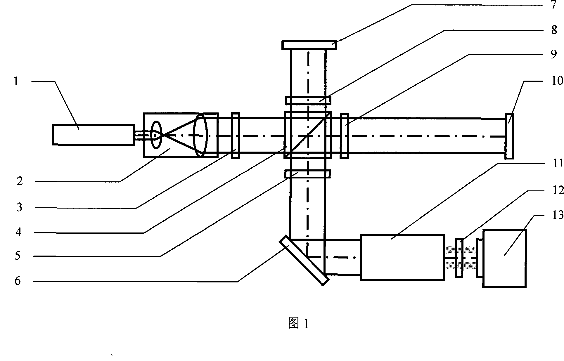
[0015] Embodiment: as shown in Figure 1, in the optical interferometry of the present invention, the main body of spectroscopic, imaging and synchronous phase-shifting device is a Twyman-Green type laser plane interferometer, and used laser light source 1 is a frequency-stabilized laser of an output polarized laser beam After the laser beam passes through the beam expander system 2, a linearly polarized plane light source is obtained. After the linearly polarized plane light source passes through the half-wave plate 3, it is divided into two parts of linearly polarized light whose polarization directions are perpendicular to each other by the polarization beam splitter prism 4. Wherein the linearly polarized light reflected by the polarization beam splitter 4 passes through the quarter-wave plate 8 and projects to the standard reference mirror 7, and passes through the quarter-wave plate 8 again after returning, so that the linearly polarized light reflected by the polarization ...


PUM


Abstract

The invention discloses a method called optical interferometry about spectrometer, imaging and simultaneous phase-shifting: enlarge polarization laser beam emitted by laser source and get linearly polarized planer source, then, enter the interference system of linearly polarized planer source and get a interference field where testing wavefront and reference wavefront have collinear beam and polarization direction is vertical each other. beam of light of interference field is divide ed into 4 beams of light whose space is distributed symmetrically and whose intensity is symmetrical after passing through 1 / 4 wave plate and light dividing system of combined glass prism, the four beams of light projects to ccd focus plane after it is through polaroid analyzer, thus, we get four interference fringe pattern whose phase move 90 degrees after a sampling at a high speed. At the same time, it discloses the device using the method. According to the device and method of this invention, the principle is clear and the method is simple, the device possesses miniaturization. It realizes dynamic measuring whose optic interference is high-accuracy at the scene; it is simpler and more convenient to measure the course.

Description

technical field [0001] The invention relates to a dynamic interferometry method and device in the field of optical wavefront detection, in particular to a method and device for light splitting, imaging and synchronous phase shifting in optical interferometry. Background technique [0002] In optical wavefront interferometry, the laser is usually used as a coherent light source, and two wavefronts are generated by dividing the amplitude. One wavefront is projected to the standard reference mirror and returned to form a reference wavefront, and the other wavefront is projected to the device under test and returned to form a reference wavefront. The test wavefront, the reference wavefront and the test wavefront meet in space to form an interference field, and the digital image acquisition device records the interference field in the form of an interference fringe pattern, and the shape of the test wavefront can be obtained by analyzing the interference fringe pattern. At presen...

Claims


Application Information

Patent Timeline
Patent Type & Authority Applications(China)
IPC IPC(8): G01B9/02G01J9/02
Inventor 吴栋聂守平冯少彤
Owner NANJING NORMAL UNIVERSITY
Why Eureka
Try Eureka