Measurement method and device for displacement of model experiment based on optics

A technology of model test and displacement measurement, which can be used in the interpretation of photos and other directions, and can solve the problems of limited number of measuring points and errors.

Inactive Publication Date: 2007-09-12
CHINA THREE GORGES UNIV
View PDF0 Cites 19 Cited by
  • Summary
  • Abstract
  • Description
  • Claims
  • Application Information

AI Technical Summary

Problems solved by technology

[0002] The traditional method of displacement measurement in landslide model tests usually uses mechanical measurement or capacitive sensor measurement to obtain the displacement of the model. This method has two main shortcomings: one is that the supporting points and measuring points

Method used


Image

  • Measurement method and device for displacement of model experiment based on optics
  • Measurement method and device for displacement of model experiment based on optics

Examples


Embodiment Construction

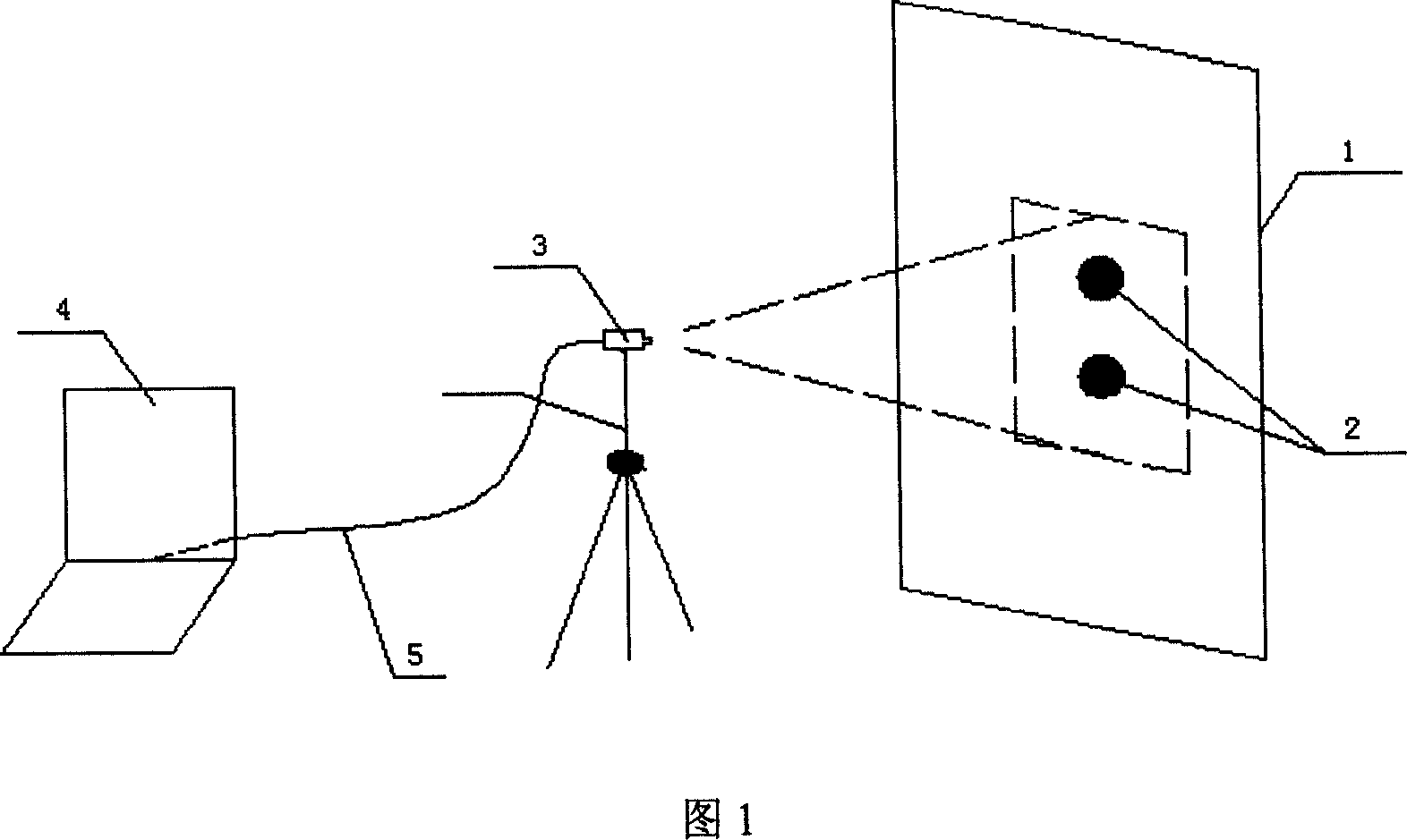
[0014] The measuring device provided by the present invention is mainly composed of a main test surface 1, a marker point 2, an imaging device 3, a computer 4, etc., and the imaging device 3 may be a video camera, a video head or a camera.

[0015] The marking point 2 arranged on the model test surface 1 is a square flat plate at the front, the wings at the rear are orthogonal to the square flat plate, and the marking pattern is a black circle spot on a white background. The marker point 2 is embedded in the model through the wing, so that the marker point 2 is always consistent with the deformation measurement point of the model. The resolution of the camera equipment 3 is not less than 352×288, and the camera is arranged at a position perpendicular to the test plane 1 and at a distance of 1 to 2 m from the test plane to ensure the effective range of the camera, so that the corresponding physical size of the digital image pixels obtained by the camera is controlled within a ce...


PUM


Abstract

This invention relates to a means and device for measuring translocation in model test. The main technical proposal is setting mark point on test model, through picture pickup device to pick picture, and dawning asynchronism image. The main technical proposal is setting mark point on test model, through picture pickup device to pick picture, and drawling asynchronism image. Admit the image to test analysis system to gain each test point translocation or transformation. This invention could real-time record transformation process of model mark point, and through digital image processing to gain higher accuracy requirement translocation. This test system can be used to process translocation measuring in higher accuracy model test.

Description

technical field [0001] The invention relates to the field of conversion and processing of optical photography and digital images, in particular to a displacement measurement method used in landslide model tests. The invention also relates to a device for carrying out measurements by such a method. Background technique [0002] The traditional method of displacement measurement in landslide model tests is usually to use mechanical measurement or capacitive sensor measurement to obtain the displacement of the model. Given enough space, the number of measuring points is very limited. Second, because the measuring instrument directly contacts the model, the measured deformation is affected by the deformation of the contact point and there is a large error. Contents of the invention [0003] The purpose of the present invention is to provide an optical measurement method that uses the principle of optics, through non-contact optical photography, and performs image processing o...

Claims


Application Information

Patent Timeline
IPC IPC(8): G01C11/06
Inventor 罗先启李宏阶张振华吴剑王志俭曹玲张峰李运江涂鹏飞
Owner CHINA THREE GORGES UNIV
Why Eureka
Try Eureka