
Dynamic micromixer

A technology of reactors and anaerobic reactors, applied in the direction of mixers, biochemical instruments, chemical instruments and methods, etc., can solve problems such as disadvantages and death, and achieve the effects of reducing heat loss, clear temperature and remarkable effect

Inactive Publication Date: 2007-09-19
赖因哈特·冯·努登舍尔德
View PDF4 Cites 1 Cited by
  • Summary
  • Abstract
  • Description
  • Claims
  • Application Information

AI Technical Summary

Problems solved by technology

[0028] n) Methane bacteria are sensitive to temperature changes. Therefore, when the high temperature > 50°C formed under the heating device (such as a heating tube) and the gas blown in will be unfavorable to them, or cause their death - this negative The effect is more obvious

Method used


Image

  • Dynamic micromixer
  • Dynamic micromixer

Examples


Embodiment Construction

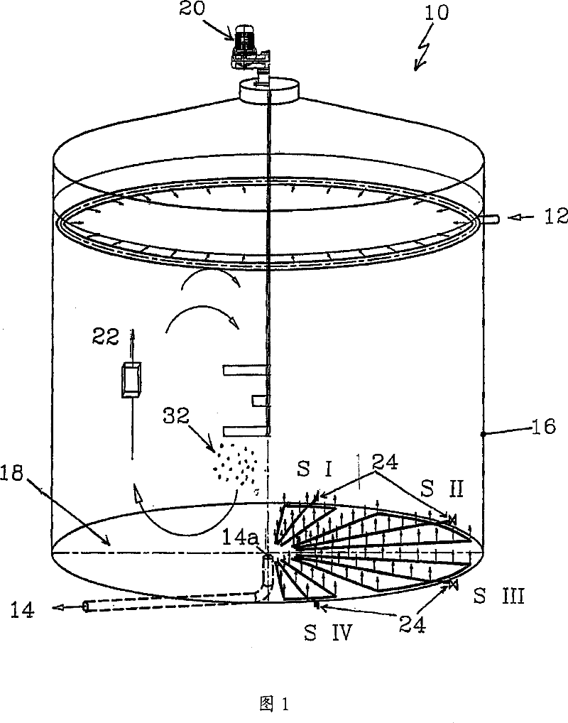
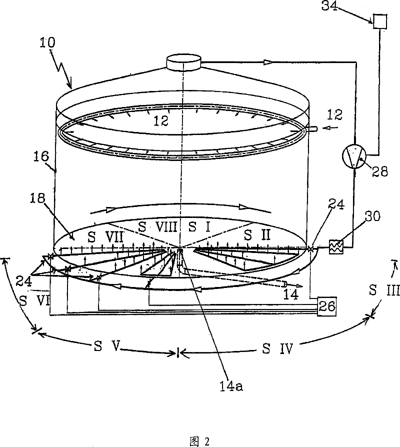
[0056] In Fig. 1, a circular biogas generator 10 is shown in perspective, wherein, the left side of Fig. 1 is a traditional overturning method carried out by means of a stirrer 20 known in the background art (only partially shown in the figure) . In the upper region of the reactor, the feed added at the feed opening 12 is turned over by the stirrer 20 according to the arrows shown in the figure on the left. After reaching the usual residence time in the reactor, the overturned biological material is discharged from the material outlet 14 at the bottom 18 of the reactor. In the background art as explained in the left half of the figure by slug flow 22, so-called flow paths (Stromfaeden) (longer vertical arrows) are formed by turning over an electric stirrer, in which, in view of the absence of internal mixing, in the reaction A complete volume of material is formed in the container. Naturally, at least part of the incoming material is also conveyed rapidly to the discharge op...


PUM


Abstract

The procedure for the fine volume-controlled blending of substrates in anaerobic reactors with flat bottoms, comprises surface-like blowing in of gas close to the reactor bottom over the entire horizontal cross-section area, and adjusting temperature of the gas for heating the reactor contents. The blowing in of the gas is distributed over sections, which completely cover the bottom of the reactor and which is alternatingly exposed to the gas in such a dynamically changing and controlled manner that at each point of volume of the reactor, a local micro-turbulence is caused. The procedure for the fine volume-controlled blending of substrates in anaerobic reactors with flat bottoms, comprises surface-like blowing in of gas close to the reactor bottom over the entire horizontal cross-section area, and adjusting temperature of the gas for heating the reactor contents. The blowing in of the gas is distributed over sections, which completely cover the bottom of the reactor and which is alternatingly exposed to the gas in such a dynamically changing and controlled manner that at each point of volume of the reactor, a local micro-turbulence is caused. The regulation of the sections for exposure to the gas takes place by a determination of the gas quantity through the particular sections in alternating time intervals. The regulation of the temporal changes takes place by several frequency-regulated gas compressor. The substrate feeding into the reactor takes place evenly over the top of the entire horizontal reactor cross-section area, in order to facilitate a plug flow of the substrate that is directed vertically downwards. Several reactors are inter-connected sequentially as a group in such a manner that the gas exposure of a reactor is increased by additionally using the gas quantity of another reactor in this reactor. A cooling process is undertaken in a permissible range for the regulation of the temperature of the gas.

Description

technical field [0001] The fields of application covered by this patent application relate to the mixing of the contents of large vessels to optimize biochemical operations in anaerobic processes, especially for the formation of biogas. Biogas formation processes of this type are increasingly being established and operated, which allow the biodecomposition of organic materials by forming biogas (mainly methane) while generating energy. This application relates to the purification of waste water decomposed from waste water-containing feedstocks to be combined with organic residues, such as the applicant's gas generation (Skjldgas)-FFF-system according to EP0998430 (see solid-fluid-fermentation process of EP1419995)) to anaerobic fermentation dedicated to the decomposition process of plants such as corn, rye, grass and the like, and other similar processes, which are often ensiled perennial as so-called NOWARO (renewable raw material) for biogas generation device. In the case...

Claims


Application Information

Patent Timeline
IPC IPC(8): C02F3/28C12M1/04C12M1/107
CPCB01F3/04106B01F3/04531B01F7/00341B01F7/16B01F2003/04673C02F3/006C02F11/04C02F2209/02C02F2209/38C12M21/04C12M23/58C12M29/06C12M29/24C12M41/20C12M47/20B01F23/231B01F23/233B01F23/23362B01F27/113B01F27/80
Inventor 赖因哈特·冯·努登舍尔德
Owner 赖因哈特·冯·努登舍尔德
Learn More