Different capacitance impeller-type internal combustion engine

An internal combustion engine, impeller type technology, applied in the direction of internal combustion piston engine, combustion engine, machine/engine, etc., can solve the inconvenient maintenance, the air intake can not meet the requirements of full combustion of fuel, and it is difficult to achieve the working volume ratio, etc. problem, to achieve the effect of improving engine performance

Inactive Publication Date: 2007-09-26
杨长吉
View PDF0 Cites 2 Cited by
  • Summary
  • Abstract
  • Description
  • Claims
  • Application Information

AI Technical Summary

Problems solved by technology

However, the increase of the supercharging device makes the structure of the engine complex and inconvenient to maintain
These shortcomings are all determined by the structure of the reciprocating piston internal combustion engine itself, that is, the air intake during the intake process cannot meet the requirements for full combustion of fuel, and it is difficult to achieve the best working volume ratio.

Method used


Image

  • Different capacitance impeller-type internal combustion engine
  • Different capacitance impeller-type internal combustion engine
  • Different capacitance impeller-type internal combustion engine

Examples


Embodiment Construction

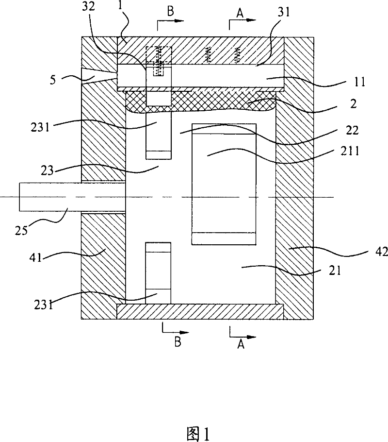
[0026] Referring to Fig. 1, the differential impeller internal combustion engine of the present invention includes a body 1 and a rotor 2 that can rotate relatively in the body 1, and end covers 41, 42 positioned at both ends of the rotor, and the engine outputs power through the rotation of the rotor 2.

[0027] The rotor 2 includes a compression section 21 and a working section 23 arranged axially. The compression section 21 realizes suction and compression, and provides compressed gas, such as air, atomized fuel oil, natural gas or a combination thereof, for the working section 23. The working section 23 realizes work and exhaust, and drives the rotor 2 to rotate.

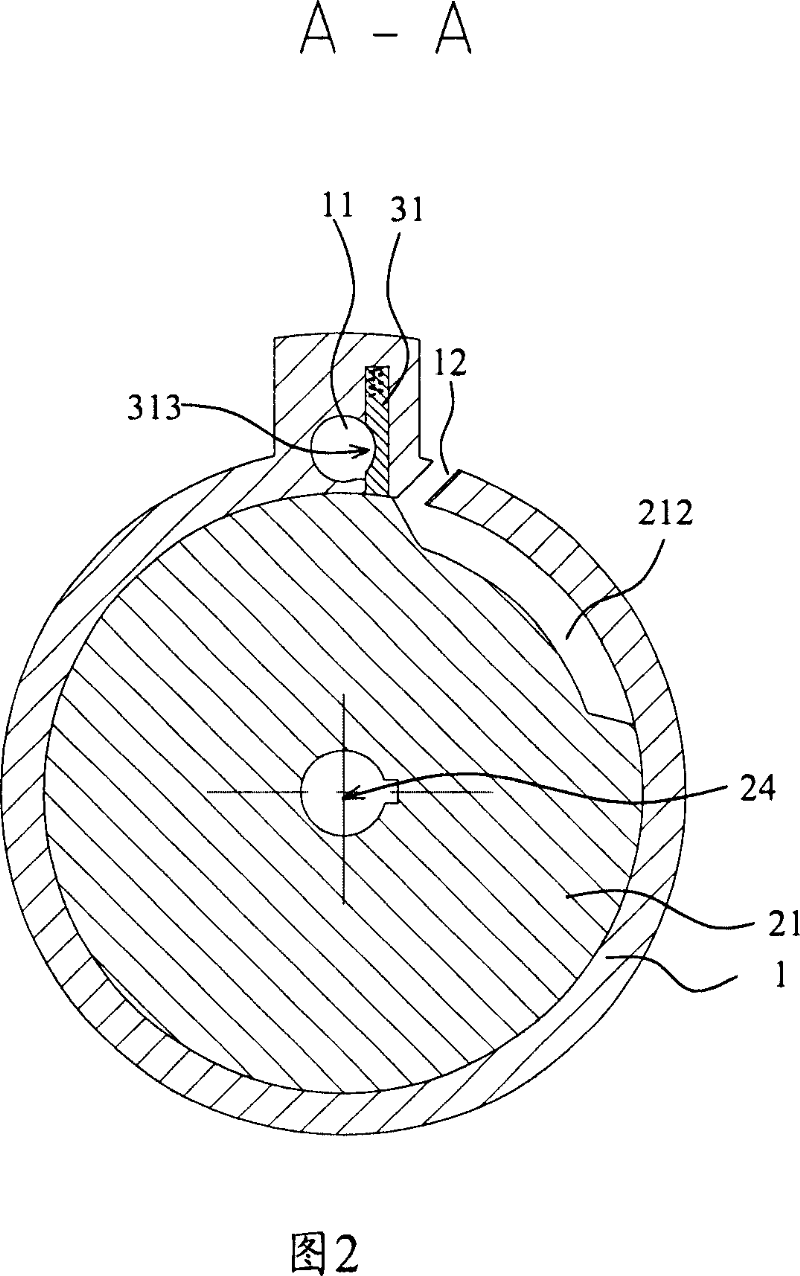
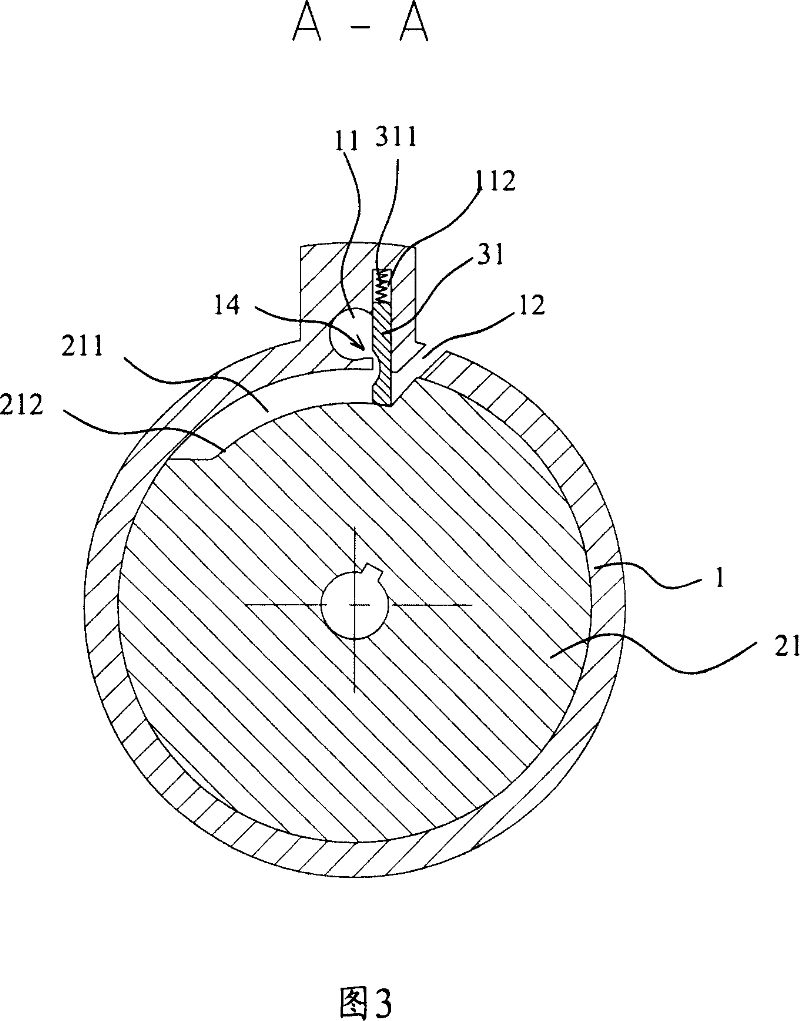
[0028] The compression section 21 of the rotor 2 is characterized by an annular groove area 211, and the annular groove area 211 extends on a part of the circumferential surface of the rotor 2. For example, the circumferential surface occupied by the annular groove area 211 corresponds to a central angle of 60 de...


PUM


Abstract

A vane internal combustion engine comprises the body and rotor relatively moving inside the body with ring slots, burning chamber on the body and connected with ring slots, shrinkable no.1 and no.2 active valve with air sealing ring slots, with size of the sealed valve by the compression ring slot along with the rotation of the rotor when the ring slot made by the compression forging connects to the burning chamber, size sealed by the active valve shrinks and gas compressed into the burning chamber, and the second active valve opens with the end of the compression, and the gas burns at the starting point of the ring slot to push the rotor continuing running. It is simple and reliable with optimal working capacity ratio to improve working efficiency.

Description

technical field [0001] The invention relates to an internal combustion engine, in particular to a differential impeller type internal combustion engine. Background technique [0002] Ordinary reciprocating piston internal combustion engines are widely used in various technical fields, and its working process—inhalation, compression, work, and exhaust—is completed by the piston in the same cylinder. Since the volume of the cylinder is fixed, the volume of suction and compression is equal to the volume of work and exhaust. This structure brings some disadvantages. For example, in order to fully burn, the engine cylinder needs to inhale a sufficient amount of air, and the cylinder is moved by the piston. The formed negative pressure inhales the air, but because the inhalation time is very short, the air has no time to fill the cylinder, resulting in insufficient air volume for fuel combustion and incomplete fuel combustion. [0003] In order to allow the piston to inhale enoug...

Claims


Application Information

Patent Timeline
Patent Type & Authority Applications(China)
IPC IPC(8): F02B53/02F02B55/02F02B55/08F02B55/14
CPCY02T10/17Y02T10/12
Inventor 杨长吉
Owner 杨长吉
Why Eureka
Try Eureka