Hot pipe temperature measuring method

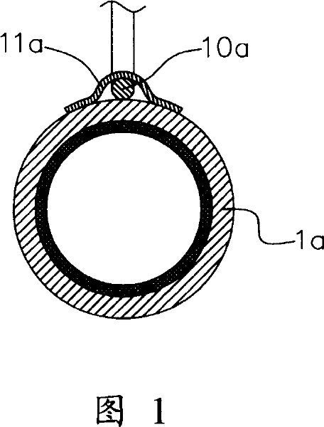
A technology of heat pipes and temperature sensing heads, which is applied in thermometers, measuring devices, and measuring heat, and can solve problems such as deformation of heat pipes 1a, affecting product quality, and damage

Inactive Publication Date: 2007-09-26
JIEFEI
View PDF0 Cites 1 Cited by
  • Summary
  • Abstract
  • Description
  • Claims
  • Application Information

AI Technical Summary

Problems solved by technology

However, when the tape 11a is to be torn off after the test is completed, it is easy to leave residual glue on the surface of the heat pipe 1a, so it is necessary to add subsequent cleaning operations, or

Method used


Image

  • Hot pipe temperature measuring method
  • Hot pipe temperature measuring method
  • Hot pipe temperature measuring method

Examples


Embodiment Construction

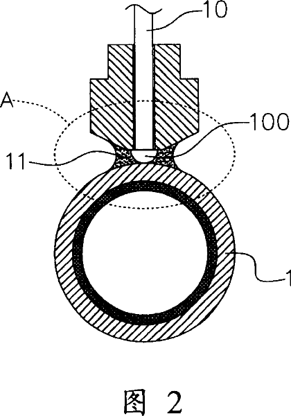
[0022] In order to further understand the features and technical content of the present invention, please refer to the following detailed description and drawings of the present invention. However, the attached drawings are only for reference and description, and are not used to limit the present invention.

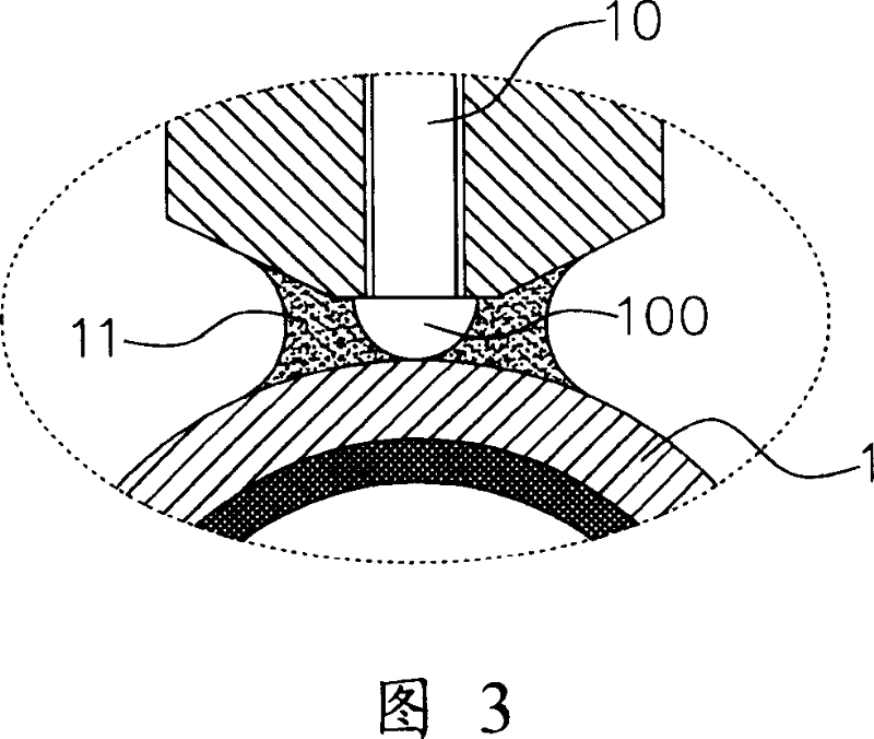
[0023] 2 and 3 are a schematic diagram of the implementation of the present invention and an enlarged view of part A of FIG. 2 respectively. The present invention provides a method for measuring the temperature of a heat pipe. The thermocouple wire 10 is firstly prepared. A temperature sensing head 100 is formed at one end of the thermocouple wire 10, and the other end is used to connect a temperature sensing device (the figure is omitted). Or record the measured temperature, and transmit the measured temperature signal to the temperature sensing device through the temperature sensing head 100 of the thermocouple wire 10.

[0024] The forming method of the temperature sensing...


PUM


Abstract

This invention relates to one thermal tube temperature test method to form temperature sensor head on one end of couple wire and to press the probe onto thermal tube and to ad proper flow medium between probe and thermal tube, wherein, the flow medium is of water, oil or sticky cream with flow property with inner polymer property to fill the gap between sensor head and thermal tube surface to add the stability property of contact resistance to lower contact thermal resistance.

Description

Technical field [0001] The invention relates to a heat pipe temperature measurement method, in particular to a heat pipe temperature measurement method for increasing the contact when detecting the surface temperature of the heat pipe and reducing the contact thermal resistance. Background technique [0002] Generally, after the manufacture of heat pipes, in order to ensure the quality of a large number of manufactured heat pipes, it is necessary to test the heat conduction amount of the heat pipes first, in order to exert the heat conduction effect. However, the conventional detection instruments or equipment are expensive in unit price, and have problems such as too complicated operation process and too long time required for detection. For example, the thermal couple wire is pasted on the surface of the heat pipe with adhesive tape. It is not possible to do full-sample testing of mass-produced heat pipes, so we can only use random inspection methods to calculate whether the po...

Claims


Application Information

Patent Timeline
IPC IPC(8): G01K7/02G01K7/10G01K7/14
Inventor 李嘉豪
Owner JIEFEI
Why Eureka
Try Eureka