Carrier body for components or circuits

A technology of carrier and circuit, applied in the field of carrier, can solve the problem of limited utilization of thermal conductivity and achieve the effect of improving the performance of resisting thermal alternation

Inactive Publication Date: 2007-09-26
CERAMTEC
View PDF0 Cites 26 Cited by
  • Summary
  • Abstract
  • Description
  • Claims
  • Application Information

AI Technical Summary

Problems solved by technology

[0005] Since a face-parallel structure is involved, the thermal conductivity can only be exploited to a limited extent

Method used


Image

  • Carrier body for components or circuits
  • Carrier body for components or circuits
  • Carrier body for components or circuits

Examples


Embodiment Construction

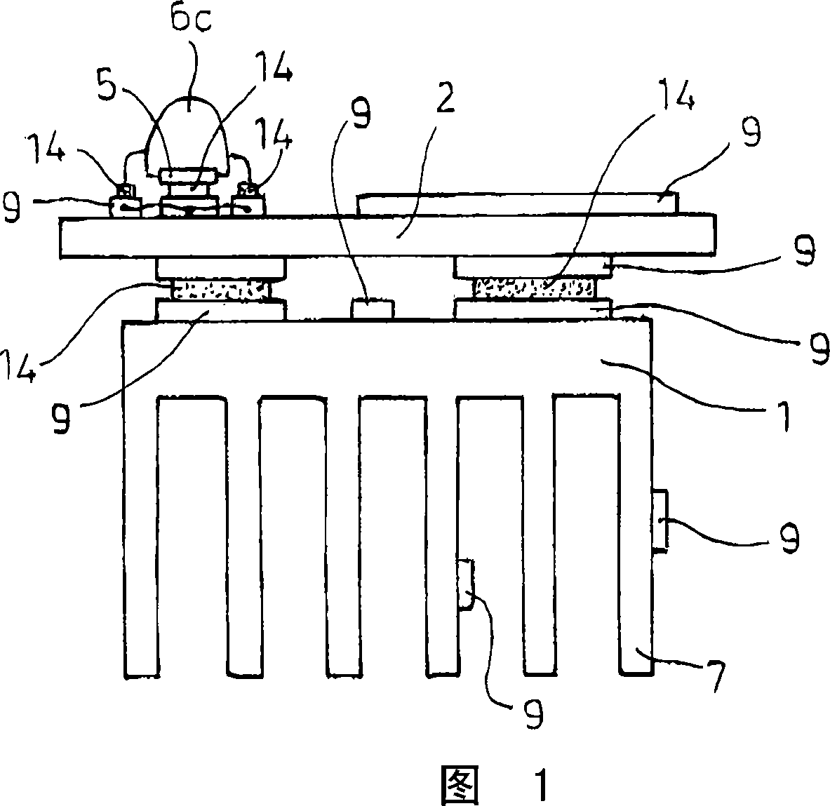
[0127] FIG. 1 shows an example of a carrier body 1 made of ceramics with a cooling element 7 made of ceramics, which is formed in one piece as a rib. On the carrier body 1 there is another independent carrier body 2 . Carrier 1 and carrier 2 each have a metal-containing, ie electrically conductive, layer 9 . The connection of the carrier body 2 to the carrier body 1 can be realized by means of a welded connection 14 . Heat dissipation or cooling of the carrier body 2 can thus take place via the carrier body 1 at the cooling element 7 . An LED 6 c can be mounted on the carrier 2 by connecting the base plate 5 of the LED 6 c to the metal-containing layer 9 of the carrier 2 via a solder connection 14 . The cooling component 7 is integrally connected with the carrier body 1 by sintering. The cooling element 7 itself can also serve as a carrier. Combinations of more than two carriers are also advantageous.

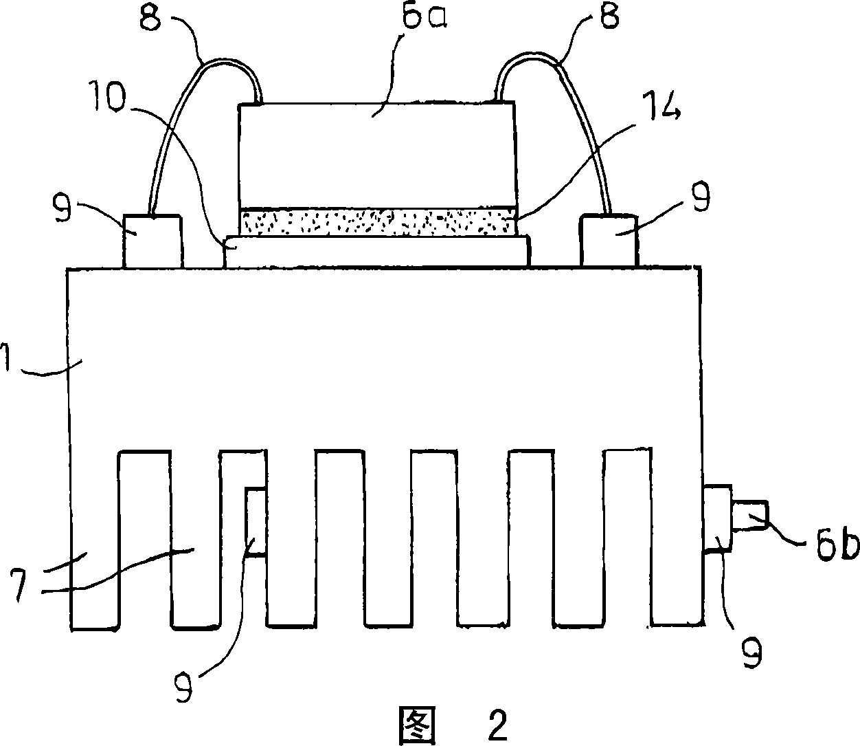
[0128] FIG. 2 shows a carrier body 1 made of ceramics with a cooling ...


PUM

PropertyMeasurementUnit
lengthaaaaaaaaaa
widthaaaaaaaaaa
thicknessaaaaaaaaaa

Abstract

The body has heat removing or heat supplying cooling units (7) in a single-piece manner, where the cooling units are channels, rips and recesses that are subjected with heating or cooling medium e.g. gas and fluid such as water or oil. The units are sintered with the body, where the body and / or the units have a ceramic component. The units are connected with the body in a spatial orientation. The set of components emitting light are connected with the body.

Description

technical field [0001] The invention relates to a carrier for electrical or electronic components or circuits, wherein the carrier is electrically non-conductive or hardly electrically conductive. Background technique [0002] According to the prior art, it is necessary to establish a planar structure for heat dissipation of high-power electronic modules, and these planar structures pass the heat emitted by the heat source (active or passive electrical components) through numerous intermediate layers (soldering, heat-conducting glue, bonding) agent, metallization) into a non-conductive, regularly shaped, geometrically simple entity (disk, rectangular base). Although the geometrical features of the individual components are simple, the overall layer structure is complex and requires the successive application of widely varying flawed processing methods such as gluing, pressing, screwing, and limits the application of welding. Each boundary layer of this stack hinders heat tr...

Claims


Application Information

Patent Timeline
Patent Type & Authority Applications(China)
IPC IPC(8): H05K7/20H05K7/02F21Y101/00
CPCF28F2215/10H01L2224/73265H05K1/0284F21V29/246H01L33/648H01L23/15H01L2924/01015H01L2224/48091F21S48/328H01L2924/01004H01L2924/01078F21Y2105/001H01L24/48H01L23/3736H01L23/3672H01L2224/32014H01L2924/01005F21K9/13H01L2924/01013H01L2224/45144H05K1/0306H01L23/552H01L23/36H01L25/162F21Y2101/02F21V29/225H01L2924/01068H05K2201/09045H01L2924/09701H01L2924/01027H01L23/3737F21V29/242H01L2924/01058H01L23/3731H01L2224/45139F21V29/26H01L23/34H05K2201/0209H01L2924/01047F21V29/004F21V29/262H01L2924/01046H01L2924/01006H01L2924/3025H01L2924/19041H01L2924/13055H01L2924/01079H01L2924/01074H01L25/16H01L2224/32245H01L33/642H01L23/367H01L2924/01082H01L2924/0104H01L2924/014H01L2924/07811H01L2924/01029H01L23/3735H01L24/32H01L2924/01019H05K1/0373H01L2924/01077H05K1/0203H01L2924/01033F21V29/2262H01L2924/0102F21V29/763F21V29/86F21V29/89H01L33/62H01L24/45H01L2924/00014H01L2924/12042H01L2924/12041H01L2924/1305H01L2924/3512F21V29/71F21V29/75F21V29/713H01L2924/00H01L2224/05599F21Y2105/10F21K9/23F21Y2115/10H01L2924/181F21V29/70H01L2924/00011H01L2224/45015H01L2924/207H01L2924/01049H01L23/373
Inventor C·P·克卢格
Owner CERAMTEC
Why Eureka
Try Eureka