
Blade seat device of slicer

A slicer and knife holder technology, which is applied in metal processing and other directions, can solve the problems that the blade rotation is greatly affected, the assembly accuracy is difficult to control, and there are many parts in the knife holder device, and the assembly is simple and fast, the assembly accuracy is easy to control, and the operation is stable. Effect

Inactive Publication Date: 2007-10-03
王荣祯
View PDF0 Cites 1 Cited by
  • Summary
  • Abstract
  • Description
  • Claims
  • Application Information

AI Technical Summary

Problems solved by technology

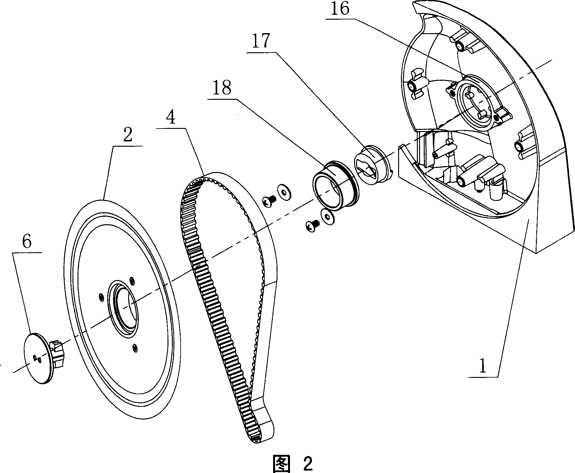
The tool seat device of this structure has many parts and high cost, and it is necessary to first fix the card slot cover 17 and the blade shaft 18, and then install the blade. The accuracy of each part has a great influence on the overall assembly. Control the matching accuracy of the blade shaft 18 and the boss 16 and the matching accuracy of the blade 2 and the blade shaft 18 respectively, so the assembly accuracy is not easy to control and has a great influence on the rotation of the blade

Method used


Image

  • Blade seat device of slicer
  • Blade seat device of slicer
  • Blade seat device of slicer

Examples


Embodiment Construction

[0025] As shown in Fig. 1, Fig. 4, Fig. 5, Fig. 6 and Fig. 7, the present invention includes a seat body 1, a blade 2, a pulley 3, a belt 4, a knife seat cover 5, a blade buckle 6, a blocking block 7, and a snap ring 8. The knife seat cover 5 is fixedly connected to the seat body 1 by screws, the pulley 3 is located in the space between the seat body 1 and the knife seat cover 5, and the center of the seat body 1 is A blade shaft 10 is provided at the center, the pulley 3 is rotatably connected with the blade shaft 10, and the blade buckle 6 is matched and connected with the blade shaft 10 to realize the limit of the blade 2 in the axial direction. The blade buckle 6 clamps the blade slot 11 so that the blade 2 is axially positioned, the snap ring 8 is fixedly connected to the blade 2 by screws, and the snap ring 8 deviates from the One side of the blade 2 is provided with an outer concave-convex gear ring 80, and the side of the pulley 3 facing the blade 2 is provided with an...


PUM


Abstract

A knife unit of slicer able to be detached and cleaned easily is composed of holder with central blade axle, a blade, a belt wheel with internal concave-convex tooth ring, a belt, a blade fastener matched with said blade axle, and a fastening ring with external concave-convex tooth ring matched with said internal one.

Description

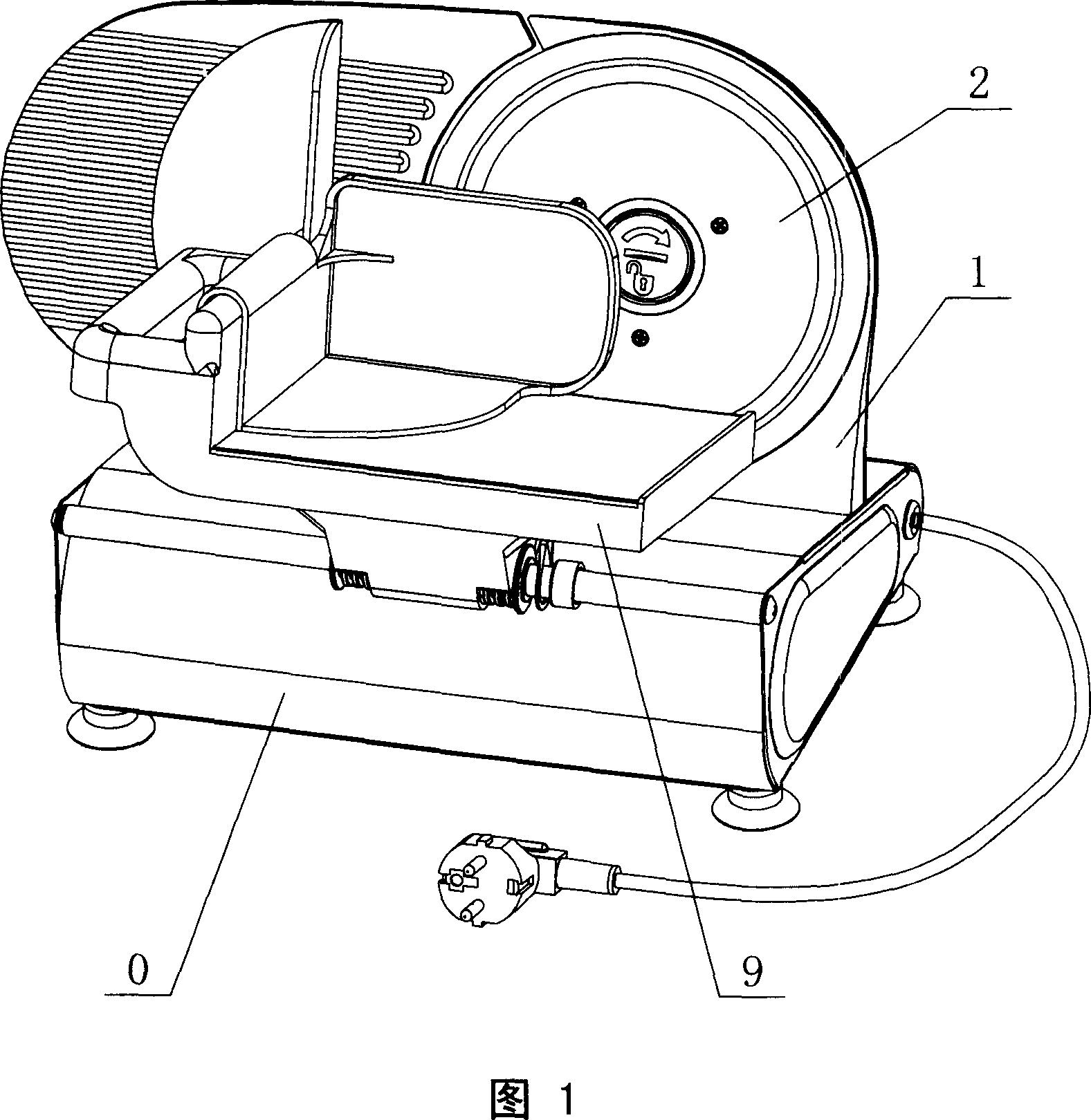
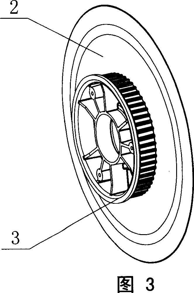
technical field [0001] The invention relates to a knife seat device of a slicer, in particular to a knife seat device of a food slicer. Background technique [0002] Food slicer is a commonly used food processing machine, which can be used to cut a variety of foods such as bread, cooked food, raw meat, sashimi, fruit, etc., especially suitable for slicing frozen meat such as beef and sheep. Well, it is currently being used more and more widely in hotels, hotels, supermarkets and homes. [0003] A kind of structure of the commonly used food slicer of existing family is shown in Figure 1, and it comprises body 0, tray 9, is used for enveloping and the knife seat device of positioning blade 2. Figure 2 and Figure 3 are schematic diagrams of a common tool holder device, which includes a seat body 1, a blade 2, a pulley 3, a belt 4, and a blade buckle 6, and the blade 2 and the pulley 3 that drives it to rotate are fixed by screws They are connected to...

Claims


Application Information

Patent Timeline
Patent Type & Authority Applications(China)
IPC IPC(8): B26D7/26B26D7/00B26D3/28
Inventor 瑞克・爱德温
Owner 王荣祯
Learn More