

Hot water pad for floor radiator and floor radiation device using the hot water pad
A hot water pad and floor heating technology, which is applied in hot water central heating systems, household heating, household heating, etc., can solve the problems of time-consuming, expensive, easy to corrode, and time-consuming, and achieve simple construction and low cost Effect
- Summary
- Abstract
- Description
- Claims
- Application Information
AI Technical Summary
Problems solved by technology
Method used
Image

Examples
Embodiment 1
[0090] Embodiment 1 (corresponding to technical scheme 1~6)
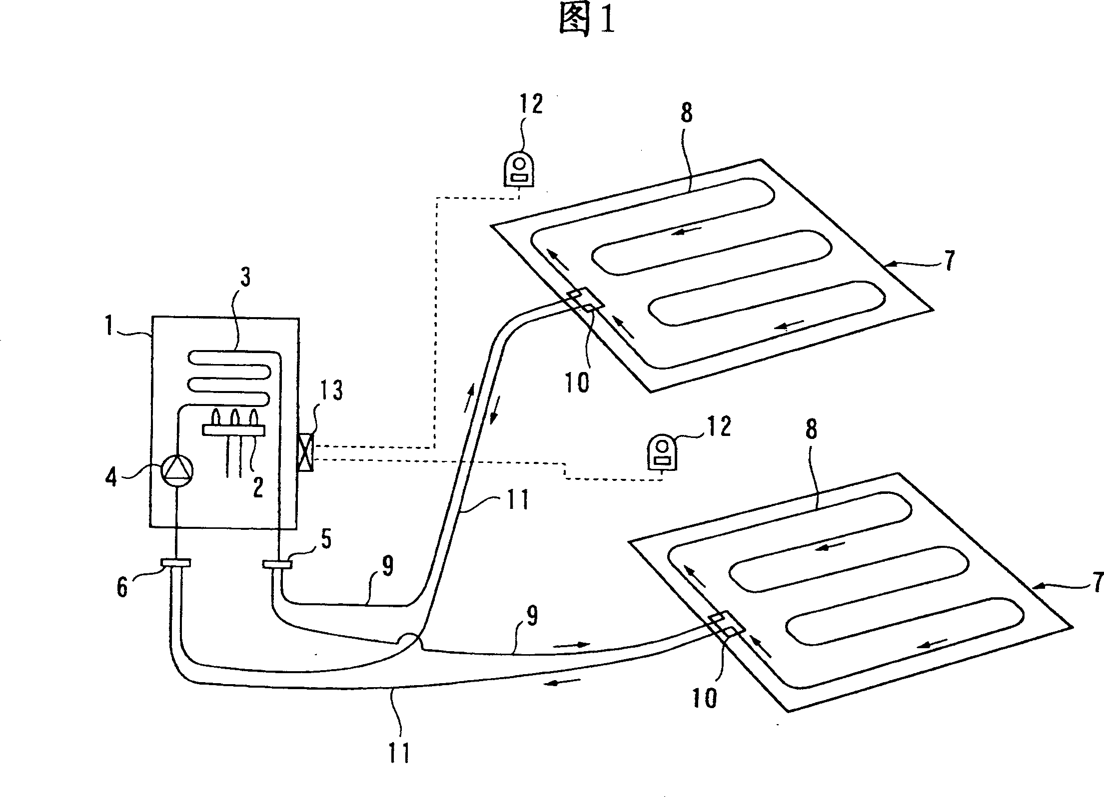
[0091] This Example 1 is an example of the invention described in Claim 1. If this embodiment 1 is described in detail according to FIG. 1, then the symbol 1 is a heat source machine, and a gas burner 2, a heat exchanger 3, and a circulation pump 4 are assembled in the heat source machine 1. 5 is used for hot water to be described later. The pad side sends out the hot water supply header of the hot water heated by the heat exchanger 3, and 6 is the hot water return header. In addition, according to construction conditions and the like, the gas burner 2 as the internal heater of the heat source machine 1 can also use an oil burner, an electric heating type, or a waste heat utilization type, etc.
[0092] 7 is a hot water pad laid in two rooms respectively, and a hot water pipe 8 is arranged in an S shape in the hot water pad 7, and the hot water sent by the hot water supply header 5 of the heat source machine 1 is s...
Embodiment 2
[0094] Embodiment 2 (corresponding to technical scheme 2~6)
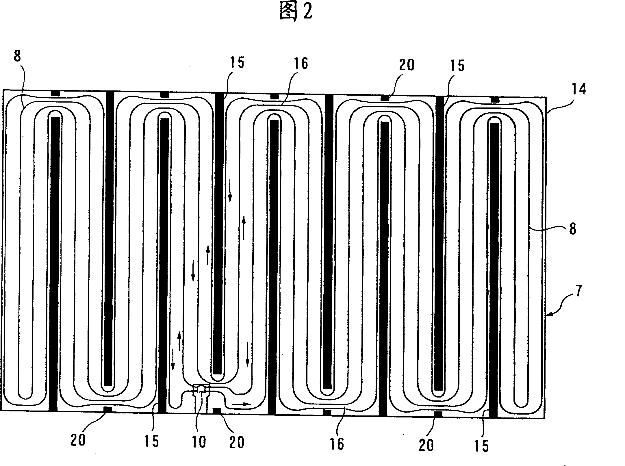
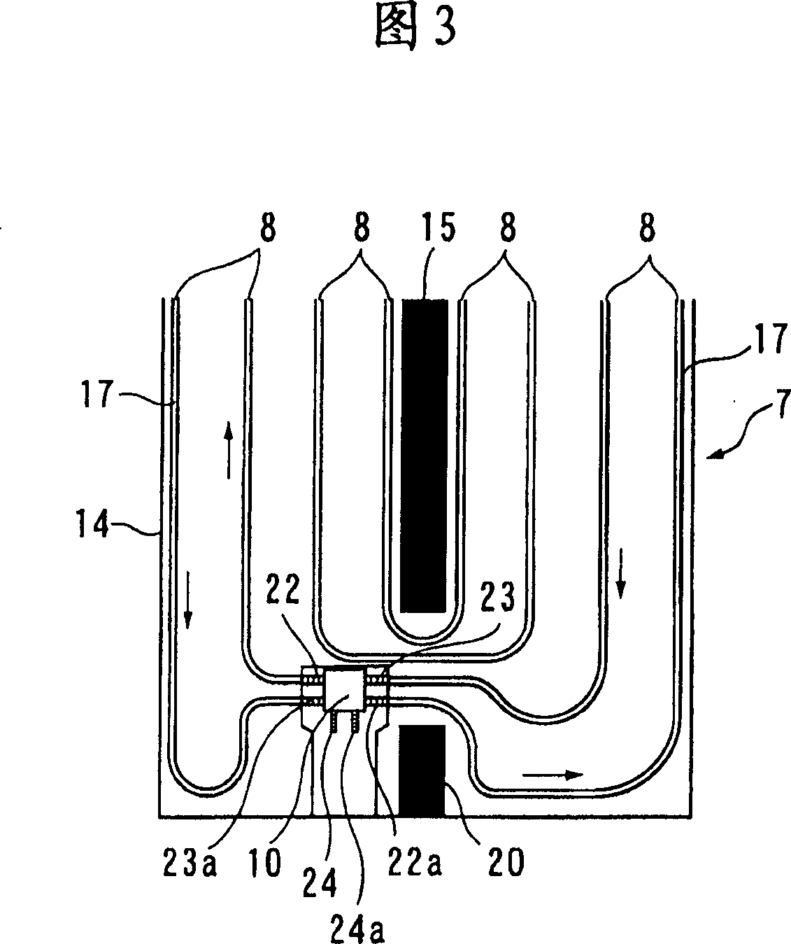
[0095] Embodiment 2 will be described in detail with reference to FIGS. 2 to 8 . In these drawings, FIG. 2 is a plan view of the pad body, FIG. 3 is a plan view of the hot water header part, FIG. 4 is an explanatory view of the small log part, and FIG. 5 is a cross-sectional view of a part of the hot water pad.
[0096] The hot water pad 7 is made of a quadrilateral pad body (assembled board) 14 processed from expanded styrene, a small wooden log 15, a piping groove 17, a resin hot water pipe 8, and a pad body 14 that is attached to the entire top of the pad body. The heat sink 19 made of aluminum foil and the small log 20 inserted into the top of the log 15 constitute. The small log 15 is alternately inserted in parallel from the upper and lower sides of the pad body 14, and its top end does not reach the opposite side, and forms a U-shaped curved space 16 between the corresponding side; the pipe groove 17 is used t...
Embodiment 3
[0103] Embodiment 3 (corresponding to technical scheme 7~10)
[0104] Embodiment 3 of the present invention will be described in detail with reference to FIGS. 9 to 12 . Fig. 9 is an overall plan view of the assembled board of the floor heating hot water pad of the present embodiment 3; Fig. 10 (a) is an explanatory diagram of the folded part of the assembled board and the cross-border part of the hot water pipe; Fig. 10 (b) is a folded assembly Figure 11 is a front view when viewed from the direction of arrow a in Figure 10(b); Figure 12 is the relationship between the pipe piping groove and the tube turning piping groove. Illustrating.
[0105] In FIGS. 9 to 12 , 100 is the main body of the floor heating assembled material. The main body 100 of the assembled material is composed of four assembled boards 101 , 102 , 103 , and 104 . The hot water pipes 102, 103, 104, as shown in Figure 9, the hot water pipes 105, 106, 107, 108 are obliquely arranged in the middle parts 101a,...
PUM
 Abstract
Description
Claims
Application Information