Microelectromechanical photoconductive interference gyro

A technology of electro-optic and microcomputer, which is used in speed measurement by gyro effect, gyroscope/steering sensing equipment, surveying and navigation, etc.

Inactive Publication Date: 2007-10-03
鄂尔多斯市嘉美科技股份有限公司
View PDF0 Cites 11 Cited by
  • Summary
  • Abstract
  • Description
  • Claims
  • Application Information

AI Technical Summary

Problems solved by technology

However, the system itself also has insurmountable defects, such as sensitivity, overcoming the Lock-in phenomenon, etc.

Method used


Image

  • Microelectromechanical photoconductive interference gyro
  • Microelectromechanical photoconductive interference gyro
  • Microelectromechanical photoconductive interference gyro

Examples


Embodiment Construction

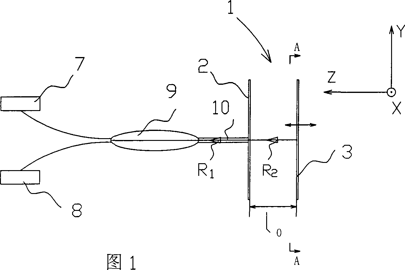
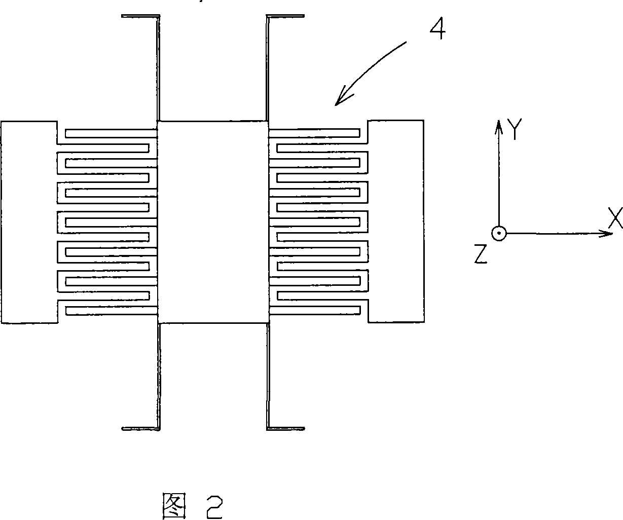
[0020] As shown in Figures 1 to 4, the micro-electromechanical photoconductive interference gyroscope of the present invention includes a vibration part that responds to Coriolis force and an optical measurement part for vibration. The vibration part 1 is composed of a vibrator 3, a vibrator excitation device 4 and a base 2. , the vibrator is supported on the base by a micro-vibration beam, there is a gap l0 between the vibrator and the base, the excitation direction of the vibrator is parallel to the base, the vibrator has a total reflection surface 5 relative to the base surface; the base 2 has a reflection surface parallel to the vibrator surface The semi-reflective surface 6 has a laser source 7 and a photosensitive element 8 on the base, which are respectively connected to a beam splitter 9, and the beam splitter is connected to a single-mode optical fiber or light guide 10 with a semi-reflective surface. Figure 2 shows that the vibrator and the excitation device are comb ...


PUM


Abstract

The microelectromechanical photoconductive interference gyro includes one force responding vibration unit and one optical vibration measuring unit. The vibration unit consists of one vibrator, one vibrator excitor and one substrate. The vibrator is supported with a beam on the substrate with some interval in between, and has excitation direction parallel to the substrate and a totally reflecting surface opposite to the substrate. The substrate has a half-reflecting surface opposite to the vibrator surface, and possesses a laser source, a photosensitizing element, a light splitter connected to the laser source and the photosensitizing element, and one monomode fiber or light waveguide with half-reflecting surface and connected to the light splitter. The microelectromechanical photoconductive interference gyro has small size and high sensitivity. The present invention gives the relation between the light intensity and the angular speed for the first time.

Description

technical field [0001] The invention relates to a gyroscope, in particular to a microelectromechanical photoconductive interference gyroscope. Background technique [0002] The development of MEMS is the miniaturization process of sensors, which has been realized in the application of pressure sensors and acceleration sensor devices. But for the existing Sagnac-type fiber optic gyroscope, miniaturization has become the bottleneck of development. Since the measurement sensitivity of the fiber optic gyroscope is determined by the length of the internal transmission fiber, it needs several kilometers of fiber in practical application, but too long fiber will bring corresponding loss and excessive noise. In order to miniaturize gyroscopes, the dependence on optical path length must be overcome. [0003] On the other hand, capacitive MEMS gyroscopes have already met the requirements of miniaturization and integration. It uses the Coriolis force to change the distance between t...

Claims


Application Information

Patent Timeline
Patent Type & Authority Applications(China)
IPC IPC(8): G01C19/56G01C19/5642
Inventor 孙博华张渤
Owner 鄂尔多斯市嘉美科技股份有限公司
Why Eureka
Try Eureka