Magnetoelectric coupling device

A magnetoelectric coupling and piezoelectric device technology, applied in the direction of electrical components, device parts, device material selection, etc., to achieve the effect of expanding the application range and improving sensitivity

Inactive Publication Date: 2007-10-03
CITY UNIVERSITY OF HONG KONG
View PDF0 Cites 8 Cited by
  • Summary
  • Abstract
  • Description
  • Claims
  • Application Information

AI Technical Summary

Problems solved by technology

However, limited by the traditional thinking mode of finding breakthroughs from composite mater...

Method used


Image

  • Magnetoelectric coupling device
  • Magnetoelectric coupling device
  • Magnetoelectric coupling device

Examples


Embodiment Construction

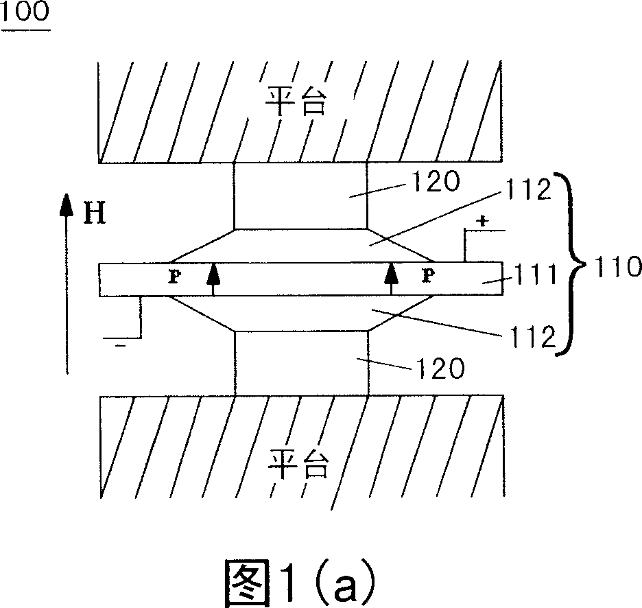
[0013] The magnetoelectric coupling device of the present invention is mainly composed of a piezoelectric device with high strain and high piezoelectric coefficient and a magnetostrictive material sheet. Here, the specific structure of the magnetoelectric coupling device of the present invention is described by taking a cymbal piezoelectric composite transducer (piezoelectric device) and a terbium dysprosium iron (magnetostrictive material) sheet as examples.

[0014] Next, the structure of the magnetoelectric coupling device of the present invention and its manufacturing method will be described with reference to FIGS. 1(a) and 1(b).

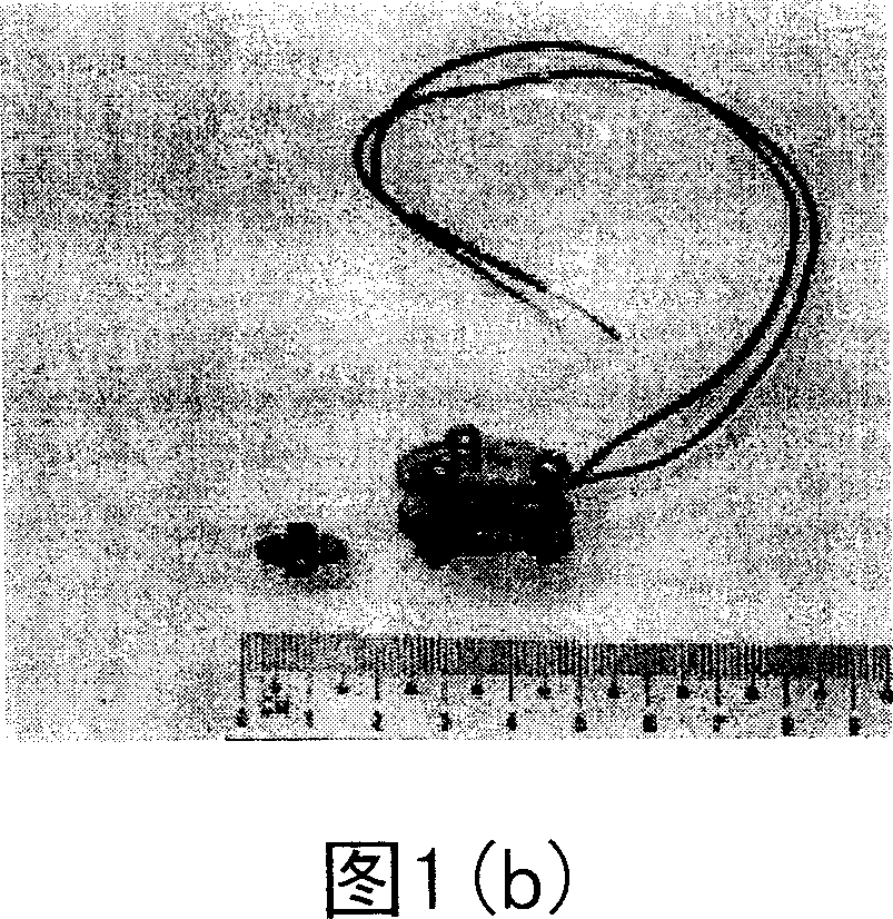
[0015] Fig. 1(a) is a schematic structural diagram of the magnetoelectric coupling device of the present invention, and Fig. 1(b) is a photograph of the magnetoelectric coupling device of the present invention.

[0016] As shown in FIG. 1( a ), the magnetoelectric coupling device 100 of the present invention includes: a cymbal piezoelectric com...


PUM


Abstract

A magneto-electric coupling component is prepared as setting piezoelectric component between two magnetostrictive plates in order to convert displacement generated by said magnetostrictive plates to be electric signal and holding said piezoelectric component being coupled together with two magnetostrictive plates by clamping fixture.

Description

technical field [0001] The invention relates to a magnetoelectric coupling device, in particular to a magnetoelectric coupling device with a high magnetoelectric coupling coefficient. Background technique [0002] In the 1980s, ferromagnetic materials with magnetostrictive effects and piezoelectric materials with piezoelectric effects were formed into composite materials, and the magnetoelectric coupling coefficient was greatly improved. Especially two kinds of materials are made into sheets, and then laminated, the performance is better (C.W.Nan, Phys.Rev.B50, 6082(1994)). The most widely used piezoelectric materials are PbZrO 3 -PbTiO 3 (Lead zirconate titanate, PZT) ceramics, BaTiO 3 Ceramic, (BaSr)Nb 2 o 6 Ceramics, Pb(Mg 1 / 3 Nb 2 / 3 )O 3 -PbTiO 3 (PMN-PT) single crystal, Pb(Zn 1 / 3 Nb 2 / 3 )O 3 -PbTiO 3 (PZN-PT) single crystal, P(VDF-TrFE) polymer, etc.; magnetostrictive materials include Tb 1-x Dy x Fe 2 (Terbium Dysprosium Iron, Terfenol-D), CoFe 2 o 4 ...

Claims


Application Information

Patent Timeline
IPC IPC(8): H01L41/00H01L41/20H01L41/18H01L41/02
Inventor 鲁圣国徐政魁国世上
Owner CITY UNIVERSITY OF HONG KONG
Why Eureka
Try Eureka