Condenser microphone circuit

A capacitive and microphone technology, applied in the direction of transducer circuits, electrical components, electret electrostatic transducers, etc., can solve the problem of not being able to obtain a large enough output signal amplitude

Inactive Publication Date: 2007-10-03
AUDIO-TECHNICA
View PDF2 Cites 7 Cited by
  • Summary
  • Abstract
  • Description
  • Claims
  • Application Information

AI Technical Summary

Problems solved by technology

Conversely, if a circuit is designed to operate optimally when the voltage of the built-in power supply battery is, for example, 1.5V, when phantom power is used, a sufficiently large output signal amplitude cannot be obtained despite the increase in the power supply voltage.

Method used


Image

  • Condenser microphone circuit
  • Condenser microphone circuit

Examples


Embodiment Construction

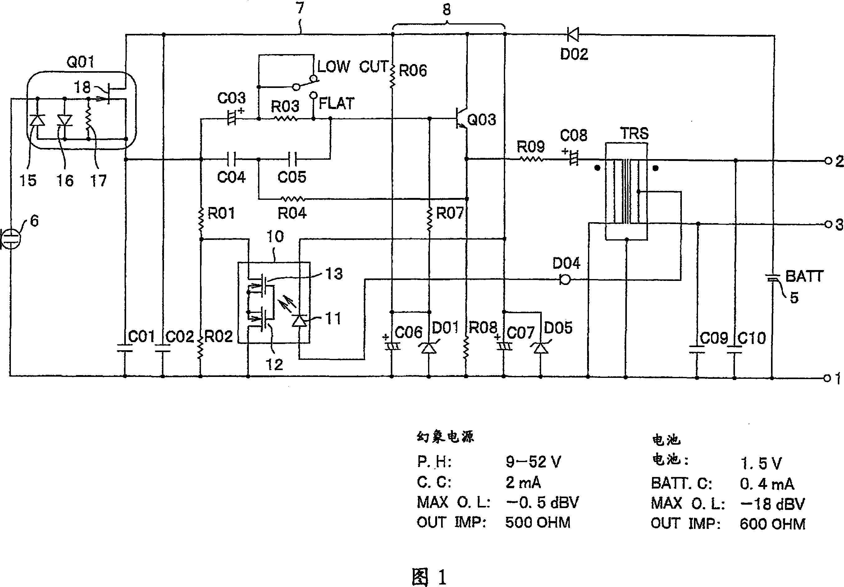
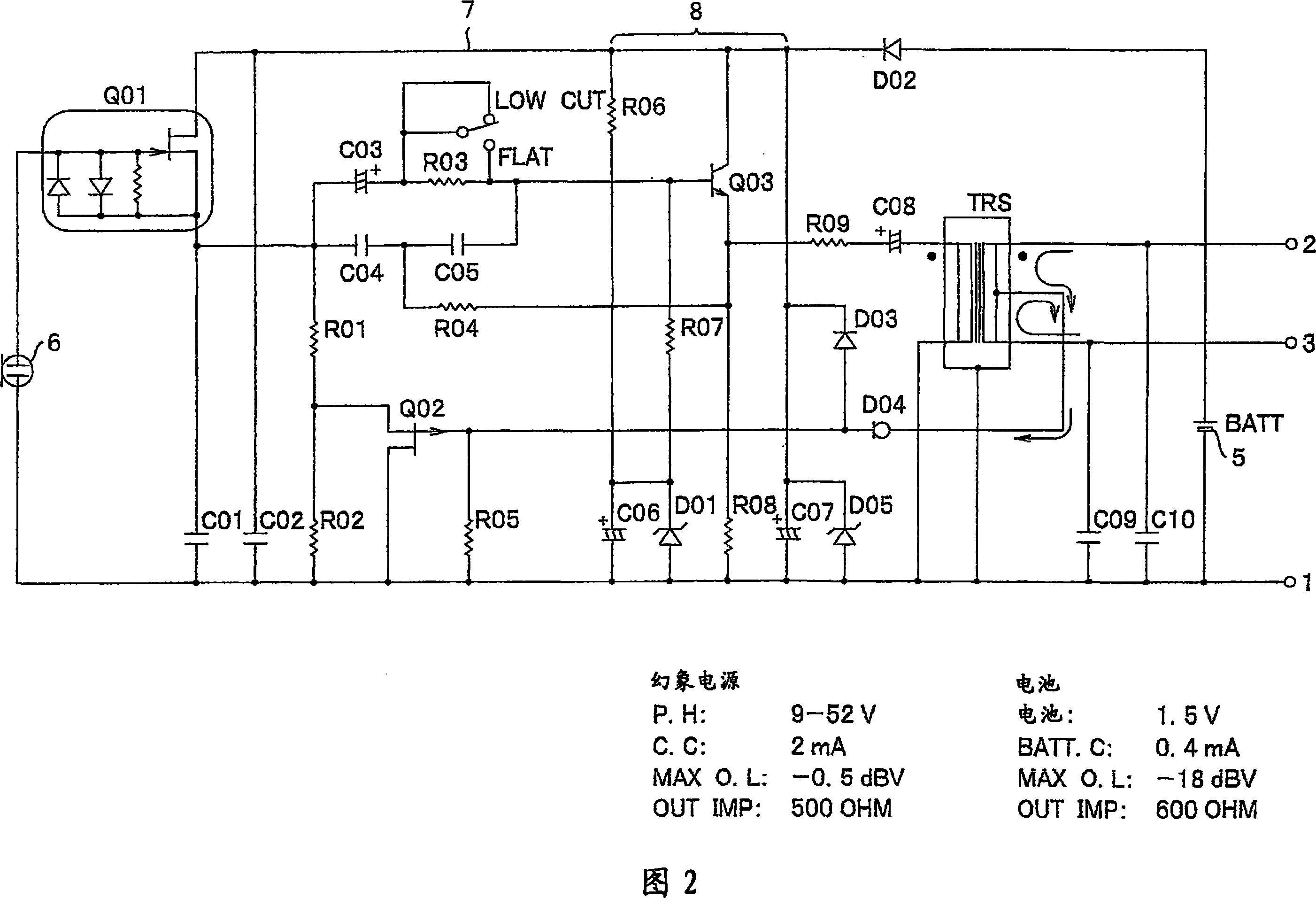
[0023] Hereinafter, embodiments of the condenser microphone circuit of the present invention will be described with reference to the drawings. The same reference numerals are assigned to the same components as those in the conventional example shown in FIG. 2 .

[0024]In Fig. 1, reference numeral 5 denotes a built-in power battery, 6 denotes a capacitive acoustic-electric conversion element, 7 denotes a power supply circuit, 8 denotes a buffer amplifier, 10 denotes an optical switch, Q01 denotes an impedance conversion element, and TRS denotes a transformer. One end of the secondary coil of the transformer TRS is connected to terminal pin 2 on the hot (Hot) side, and the other end is connected to terminal pin 3 on the cold (Cold) side. The above-mentioned terminal pin 2 and terminal pin 3 are connected to the output cord through a 3-pin type connector based on the above-mentioned EIAJ standard, for example, and the other terminal pin 1 is connected to the ground line of the m...


PUM


Abstract

In a condenser microphone which selectively uses a phantom power supply and a built-in battery power supply, and which switches load resistance elements of an impedance converter corresponding to a selected power supply, a noise due to the high frequencies is prevented from occurring even if a cellular phone or the like is used in the vicinity. The condenser microphone includes: a condenser type electro-acoustic transducer element; an impedance converter that converts an output impedance of the electro-acoustic transducer element; load resistance elements of the impedance converter; a phantom power supply and a built-in battery power supply for operating the impedance converter; a switch that switches the values of the load resistance between at the time of using the phantom power supply and at the time of using the built-in battery power supply, wherein the switch is an optical switch that turns on / off optical coupling. The optical switch is switched so that the value of the load resistance is larger at the time of using the phantom power supply than at the time of using the built-in battery power supply.

Description

technical field [0001] The present invention relates to a condenser microphone circuit, in particular to a condenser microphone circuit capable of switching between a phantom power supply and a battery used as a built-in power supply. Background technique [0002] Since the impedance of a condenser microphone unit as an acoustic-electric converter is high, an impedance converter using a FET (Field Effect Transistor, hereinafter the same) or the like is generally used for a condenser microphone. A power supply is required to operate the impedance converter. In the power supply of a condenser microphone, there are a common battery that is a power supply built into the microphone, and a mixer or phantom power supply for supplying power from the outside. The phantom power described above is supplied to the microphone via the output cord of the microphone, as specified in the Electron Machinery Industries Association of Japan (EIAJ) standard RC-8162A "Power Supply Method for Mic...

Claims


Application Information

Patent Timeline
Patent Type & Authority Applications(China)
IPC IPC(8): H04R3/00H04R1/08H04R19/01
CPCH04R3/00
Inventor 秋野裕
Owner AUDIO-TECHNICA
Why Eureka
Try Eureka