Microphone

a microphone and microphone technology, applied in the field of microphones, can solve the problems of inability to automate the entire fabrication process including dust-proof treatment, difficult to automate the cloth attachment step, and the cloth cannot endure the heating during the process, so as to achieve the effect of not reducing the sound pressure applied

Active Publication Date: 2006-08-10
HOSIDEN CORP
View PDF9 Cites 47 Cited by
  • Summary
  • Abstract
  • Description
  • Claims
  • Application Information

AI Technical Summary

Benefits of technology

[0009] Configured as described above, the pores can prevent entry of a foreign matter, such as dust or water droplets, without reducing the sound pressure applied externally. Furthermore, since the nonporous region is provi

Problems solved by technology

However, according to such a conventional dust-proof measure, a cloth has to be attached to a microphone with a double-sided tape or adhesive after fabrication of the microphone is completed.
The cloth attachment step is difficult to automate, so that the entire fabrication process including the dust-proof treatment has not been able to be automated.
In addition, the cloth cannot endure the heating during the solderin

Method used


Image

  • Microphone
  • Microphone
  • Microphone

Examples


first embodiment

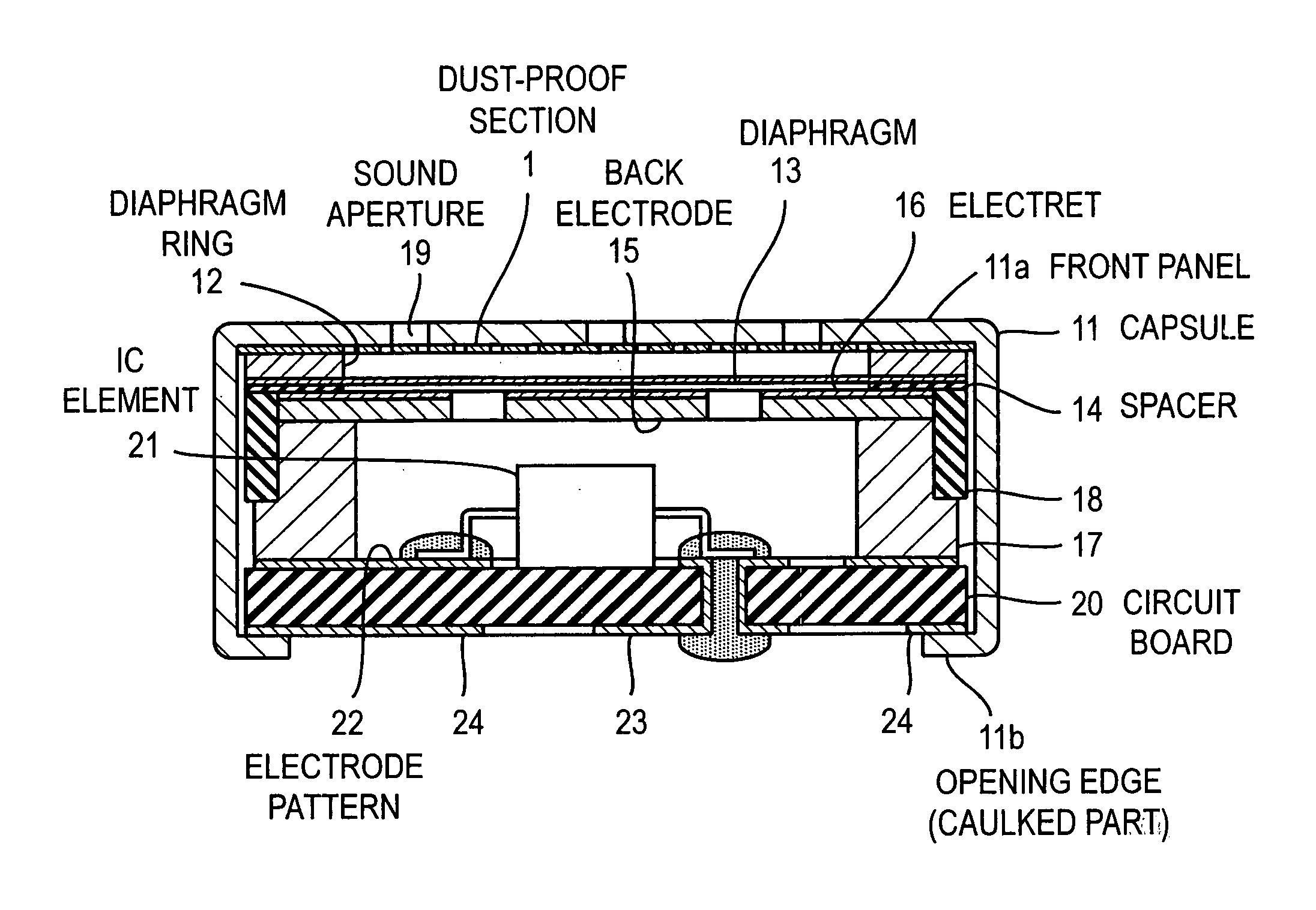
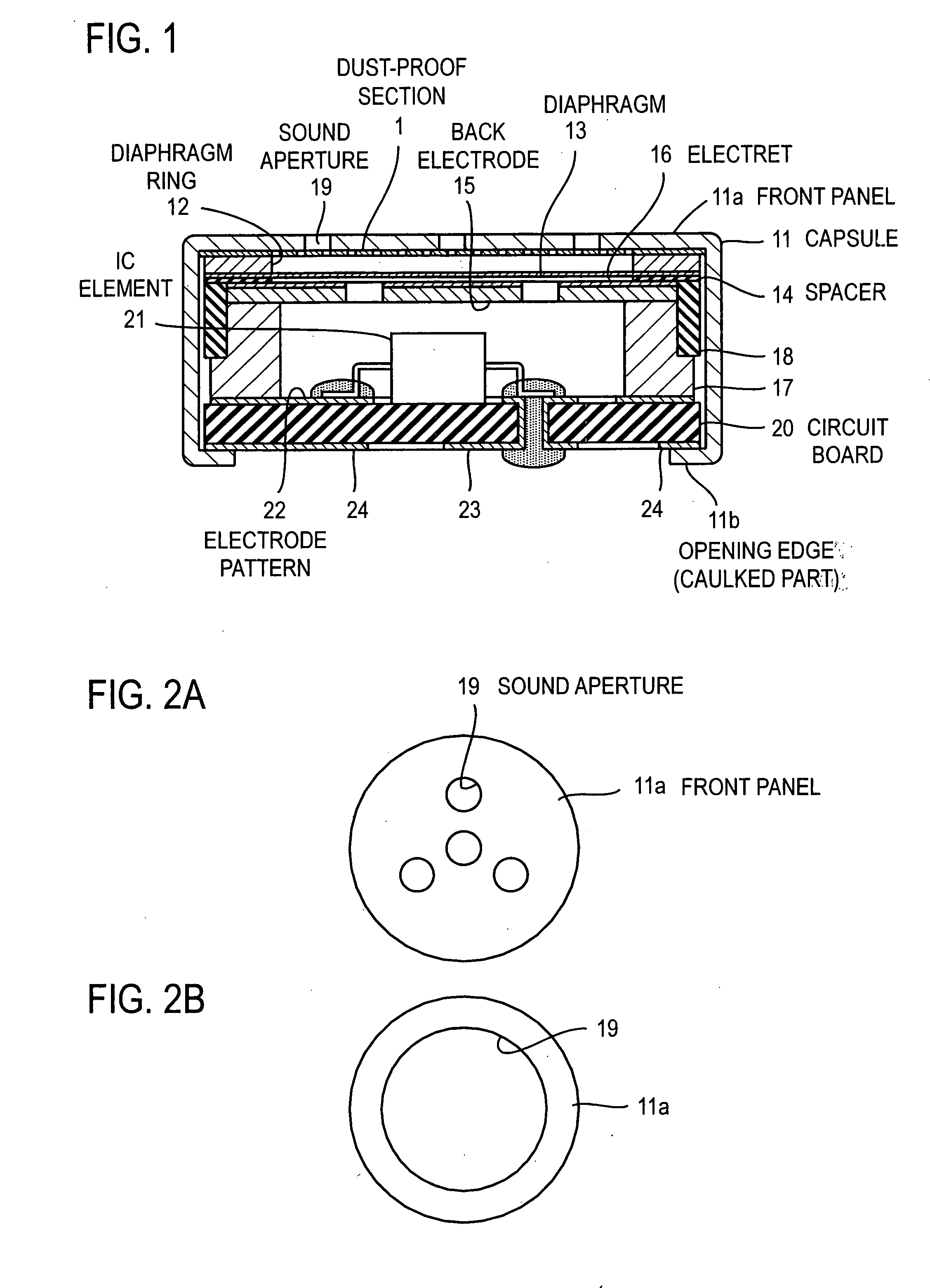
[0021]FIG. 1 is a cross-sectional view of an example of an electret condenser microphone. Referring to FIG. 1, a cylindrical capsule 11 houses an electret condenser. To house built-in components such as the electret condenser, an opening of the capsule 11, which is opposite to a front panel 11a of the capsule 11, is sealed by a circuit board 20.

[0022] Viewed from the side of the front panel 11a, the capsule 11 houses a dust-proof section 1, a diaphragm ring 12, a diaphragm 13, a ring-shaped spacer 14, a back electrode 15, an electret 16, a cylindrical conductive body 17 mounted on the circuit board 20, and an insulating ring 18 fitted on the outer peripheries of the back electrode 15 and the cylindrical conductive body 17. The electret condenser comprises the diaphragm 13 stretched on the diaphragm ring 12, the ring-shaped spacer 14, and the electret 16, which covers the surface of the back electrode 15 facing to the front panel 11a. In general, the electret 16 is made of tetrafluo...

second embodiment

[0034]FIG. 7 shows an arrangement of a microphone according to this embodiment. In the embodiment 1, the dust-proof section 1 is disposed inside the front panel 11a of the capsule 11, and then the diaphragm 13 and the back electrode 15 are disposed in this order. However, in this embodiment, a dust-proof section 1 is disposed inside a front panel 11a, and then a back electrode 15 and a diaphragm 13 are disposed in this order. Then, a diaphragm ring 12 and a gate ring 25 are disposed. An electret 16 is disposed on the surface of the back electrode 15 facing to the diaphragm 13. The diaphragm 13 is electrically connected to a circuit board via the gate ring 25. An FET element 21a and a capacitor 21b are mounted on the inner surface of the circuit board 20. In addition, a terminal substrate 20a having a step protrudes from the outer surface of the circuit board 20. This is provided to prevent a caulked part 11b from being adversely affected by melting of solder 26 in a reflow furnace. ...

third embodiment

[0035]FIG. 8 shows an arrangement in which a front panel 11a of the capsule 11 serves also as a back electrode. In this microphone, a dust-proof section 1 is disposed inside the front panel 11a, and an electret 16 is disposed inside the dust-proof section 1. Then, a diaphragm 13 and a gate ring 25 are disposed in this order. Since an integral part doubles as the back electrode and the front panel 11a, and the electret 16 is disposed on the dust-proof section 1, the microphone can be extremely thin. In this embodiment, there is provided an insulating film 27 for insulating the capsule 11.


PUM


Abstract

In order to automate a microphone assembly process including a dust-proof treatment, an object of the present invention is to provide a dust-proof microphone having a configuration suitable for automated assembly.
According to the present invention, a microphone has a plate-like or film-like dust-proof section that is disposed in a conductive housing (capsule) having a sound aperture and covers the sound aperture. The dust-proof section has a plurality of pores at least in a region corresponding to the sound aperture, and the dust-proof section further has a nonporous region. In the case of an electret condenser microphone, from the viewpoint of performance of the microphone, the dust-proof section is conductive. In addition, taking into account a soldering in a reflow furnace, the dust-proof section is heat-resistant. Each pore is desirably designed taking into account the environment for the usage of the microphone. However, if it is supposed that the microphone is used near one's mouth, each pore has an area of 0.01 mm2 or less. In addition, to enhance the dust-proof effect, the pores may be subjected to a water-repellent treatment.

Description

BACKGROUND OF THE INVENTION [0001] 1. Field of the Invention [0002] The present invention relates to an electronic device that has a dust-proof section over an opening of a housing thereof. In particular, it relates to a microphone having a dust-proof section. [0003] 2. Description of the Related Art [0004] As disclosed in Japanese Patent Application Laid-Open No. 2004-328231, it is common practice to cover a sound aperture of a microphone with a cloth, such as a nonwoven fabric, to prevent entry of a foreign matter or dust from the sound aperture. [0005] However, according to such a conventional dust-proof measure, a cloth has to be attached to a microphone with a double-sided tape or adhesive after fabrication of the microphone is completed. Thus, there exists an additional step of cloth attachment after assembly of the microphone. The cloth attachment step is difficult to automate, so that the entire fabrication process including the dust-proof treatment has not been able to be a...

Claims


Application Information

Patent Timeline
IPC IPC(8): H04R17/02
CPCH04R1/086H04R19/04E03C1/264E03C2201/40
Inventor IZUCHI, TOSHIROONO, KAZUONAKANISHI, KENSUKEONISHI, HIROAKI
Owner HOSIDEN CORP
Why Eureka
Try Eureka