Display controller and display device
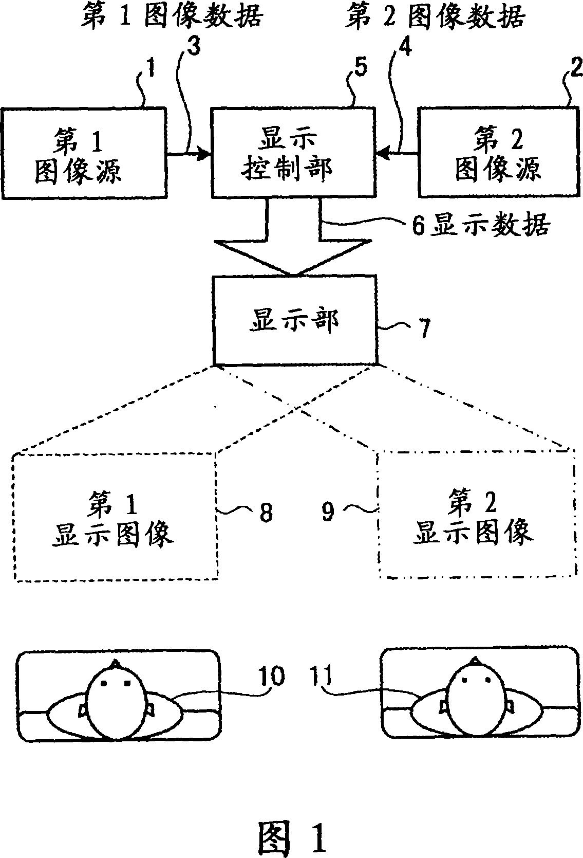
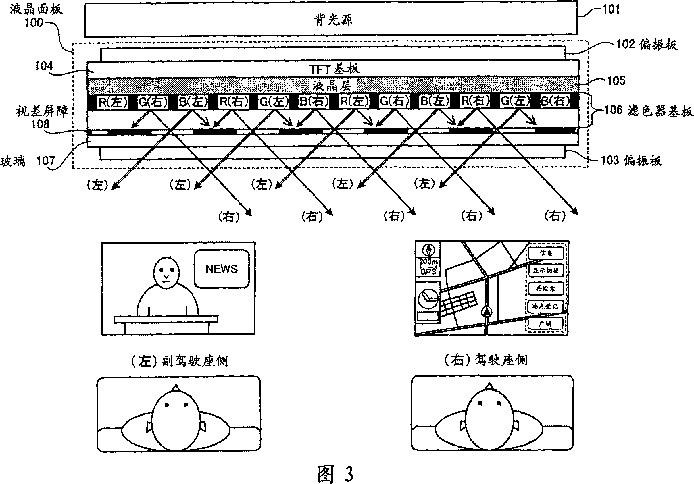
A display control and display device technology, applied to static indicators, transportation and packaging, cathode ray tube indicators, etc., can solve problems such as unclear, unsatisfactory observers, high prices, etc., to improve visibility Effect
- Summary
- Abstract
- Description
- Claims
- Application Information
AI Technical Summary
Problems solved by technology
Method used
Image
Examples
Embodiment 1
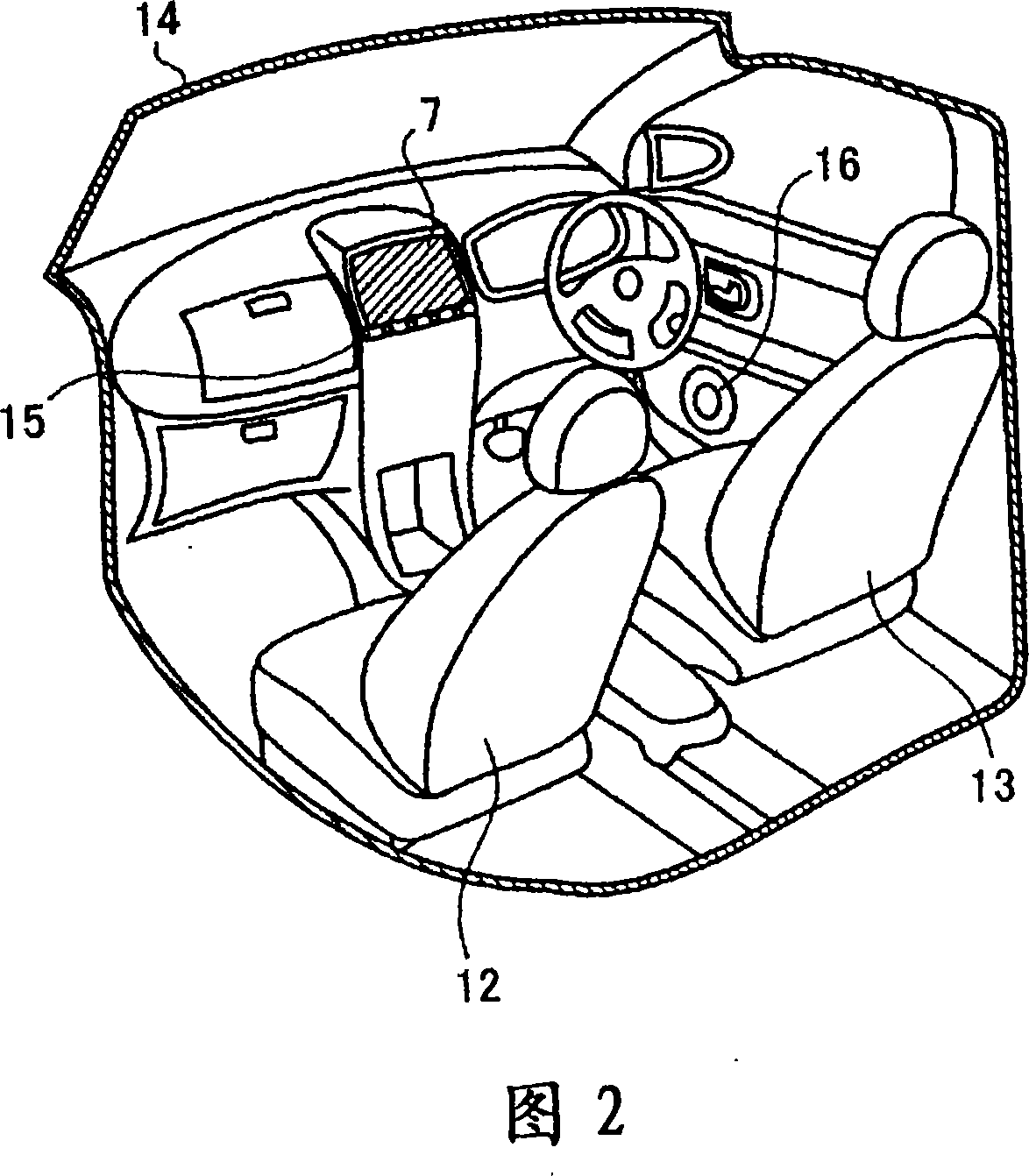
[0096] In the first embodiment, as shown in FIG. 12 , a navigation device N for guiding the vehicle to its destination and a radio wave receiver 302 for receiving terrestrial digital broadcasting are installed in the vehicle, and the navigation device N and the radio wave can be simultaneously displayed. The receiving device 302 includes a multi-view display unit 325 for displaying images, a display control device 340 for displaying and controlling the multi-view display unit 325 , an imaging device 330 for security, and the like. In addition, the display device is composed of the above-mentioned multi-view display unit 325 and the display control device 340 .
[0097] The above-mentioned navigation device N is composed of the following components: a map data storage unit 305 storing road map data, a GPS receiving unit 306 for recognizing the position information of the vehicle, a GPS antenna 306a, and an autonomous navigation unit for managing the driving state of the vehicle ...
Embodiment 2
[0142] In the second embodiment, a video signal generating unit that generates the video signal from the source signal so as to improve the video quality of a video viewed from an intermediate viewing direction between adjacent viewing directions will be described. As shown in FIG. 18, a navigation device N for guiding the vehicle to its destination, a radio wave receiving device 1302 for receiving terrestrial digital broadcasting, and a device capable of simultaneously displaying the display images of the navigation device N and the radio wave receiving device 1302 are installed in the vehicle. A multi-view display device 1340, a security imaging device 1330, and the like.
[0143] The above-mentioned navigation device N is composed of the following components: a map data storage unit 1305 storing road map data, a GPS receiving unit 1306 for recognizing the position information of the vehicle, a GPS antenna 1306a, and an autonomous navigation unit for managing the driving stat...
Embodiment 3
[0191] In the third embodiment, as shown in FIG. 30 , a navigation device N for guiding the vehicle to its destination, a radio wave receiver 2302 for receiving terrestrial digital broadcasting, and a DVD player 2303 are installed in the vehicle, and their output images are displayed. The multi-view display device 2301 is equipped with a display control device 2304 that controls the display of the multi-view display unit 2301. The display device is composed of the above-mentioned multi-view display unit 2301 and the display control unit 2304 .
[0192] The above-mentioned navigation device N is composed of the following components: a map data storage unit 2305 storing road map data, a GPS receiving unit 2306 for recognizing the position information of the vehicle, a GPS antenna 2306a, and an autonomous navigation unit for managing the driving state of the vehicle 2307, the route search unit 2308 for searching the route to the designated destination according to the map data, t...
PUM
 Abstract
Description
Claims
Application Information
 - R&D
- Intellectual Property
- Life Sciences
- Materials
- Tech Scout
- Unparalleled Data Quality
- Higher Quality Content
- 60% Fewer Hallucinations
Browse by: Latest US Patents, China's latest patents, Technical Efficacy Thesaurus, Application Domain, Technology Topic, Popular Technical Reports.
© 2025 PatSnap. All rights reserved.Legal|Privacy policy|Modern Slavery Act Transparency Statement|Sitemap|About US| Contact US: help@patsnap.com


