
Biomass fuel steam and hot water boiler

A biomass fuel and hot water boiler technology, which is applied in the direction of grates, incinerators, combustion types, etc., can solve the problems of not being suitable for burning biomass fuels, and achieve the goals of preventing black smoke, reducing pollution, and improving combustion efficiency Effect

Inactive Publication Date: 2007-10-10
葫芦岛市华东锅炉有限公司
View PDF0 Cites 4 Cited by
  • Summary
  • Abstract
  • Description
  • Claims
  • Application Information

AI Technical Summary

Problems solved by technology

The steam boiler with this structure can only use coal as fuel, not suitable for burning biomass fuel

Method used


Image

  • Biomass fuel steam and hot water boiler
  • Biomass fuel steam and hot water boiler
  • Biomass fuel steam and hot water boiler

Examples


Embodiment Construction

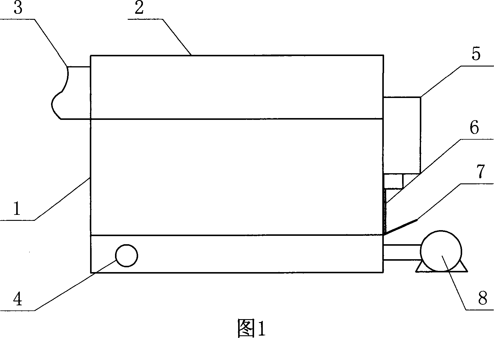
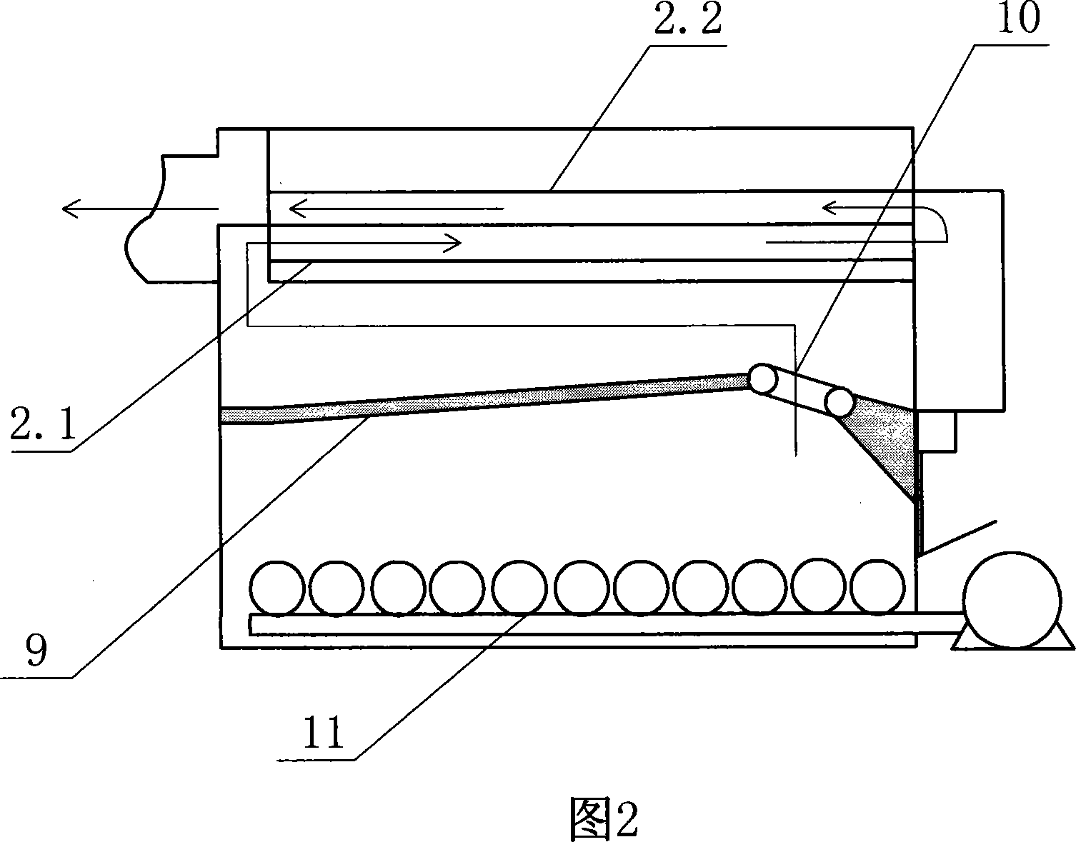
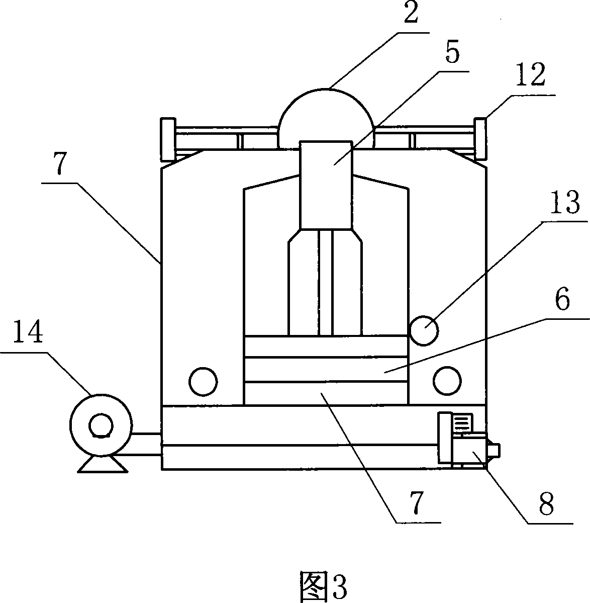
[0020] As shown in Figures 1, 2 and 3, an evaporator 2 is installed on the upper part of the furnace body 1, an air inlet 4 is arranged on one side of the lower part, a blower 14 is installed on the air inlet, and a return air cavity 5 is arranged on the front side of the furnace body. , a furnace mouth is provided at the bottom of the air return chamber, a furnace door 6 is installed on the furnace mouth through a furnace door opening and closing turntable 13, a furnace mouth guide plate 7 is connected to the lower side of the furnace door, and a power machine 8 is installed at the lower part of the front side of the furnace body A display instrument 12 is connected and installed on the upper side of the furnace body; a vault 9 is provided at the upper middle part of the furnace body furnace, and a secondary air inlet pipe 10 is installed on the vault.

[0021] As shown in Figure 4, the secondary air inlet pipe 10 is composed of four-sided closed tubular objects connected to e...


PUM


Abstract

A steam and hot water boiler of biological material fuel type is prepared for setting secondary air inlet pipe with air inlet hole on fornication of furnace tank, transmission-connecting engine to rolling fire gate at one side of furnace body through driving handle, distributing a numbers of rolling bushing teeth on rolling bushing of rolling fire grate and distributing ventilation holes between rolling bushing teeth.

Description

technical field [0001] The invention provides a biomass fuel steam and hot water boiler for providing steam in the thermal field. Background technique [0002] Before the present invention was proposed, coal was usually used as fuel in steam boilers and hot water boilers. Because coal has high calorific value and less volatile matter, it is beneficial to provide air supply conditions, and its structure is relatively simple. The structure of a typical coal-fired steam boiler is: a combustion chamber is provided in the furnace body, and heating pipes are arranged and connected around the combustion chamber. Both sides of the fire grate are respectively connected with transmission chains and connected with the transmission shaft and the power machine. The steam boiler with this structure can only use coal as fuel, and is not suitable for burning biomass fuel. Contents of the invention [0003] In order to obtain steam and hot water by using biomass as fuel, the present inve...

Claims


Application Information

Patent Timeline
Patent Type & Authority Applications(China)
IPC IPC(8): F23G5/44F23H9/00
Inventor 张伟刘书真崔桂娟李连海刘璐
Owner 葫芦岛市华东锅炉有限公司
Learn More