Method for producing novel high precision optical fiber array

An optical fiber array and manufacturing method technology, which is applied to the coupling of optical waveguides and other directions, can solve the problems of difficulty in grasping the amount of adhesive added to the upper cover plate 22, complex process, difficulty in mass production, etc., and is suitable for mass production. , the process is simple, the effect of reducing the production cost

Inactive Publication Date: 2007-10-10
BROADEX TECH
View PDF1 Cites 16 Cited by
  • Summary
  • Abstract
  • Description
  • Claims
  • Application Information

AI Technical Summary

Problems solved by technology

[0005] The above method can make the accuracy of the optical fiber array reach about 0.5 microns, but the disadvantage is that it is difficult to grasp the amount of adhesive added to the upper cover plate 22
If the added amount is insufficient, the optical fiber may fall off; if the added amount is large, the adhesive may flow into the V-groove mold 24, resulting in a decrease in the accuracy

Method used


Image

  • Method for producing novel high precision optical fiber array
  • Method for producing novel high precision optical fiber array
  • Method for producing novel high precision optical fiber array

Examples


Embodiment Construction

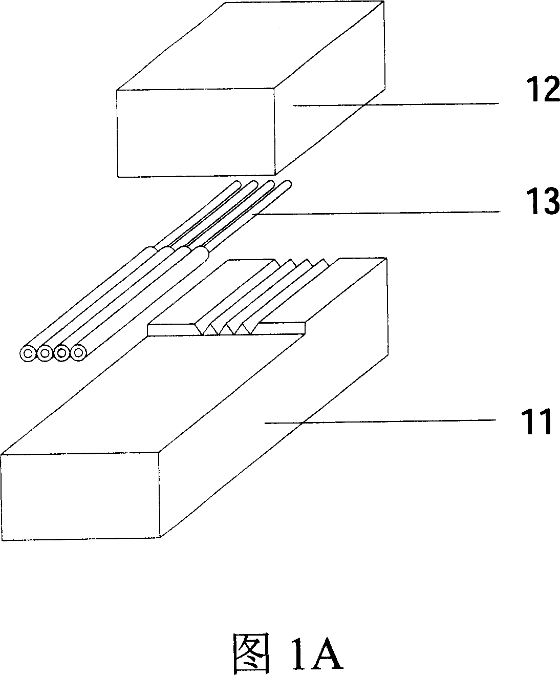
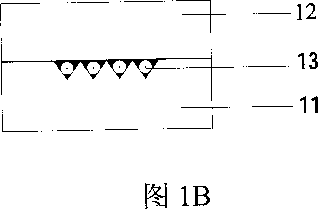
[0022] The current standard specifications for single-mode fiber are: coating diameter of 250 microns, cladding diameter of 125 microns and core diameter of 9 microns. According to the different requirements of the fiber core spacing, there are two standard specifications for the fiber array: 250 microns and 127 microns. Two arrangements are thus produced, please refer to Fig. 3, Fig. 3A shows the situation that the front and rear ends of a kind of optical fiber ribbon are all single layers (corresponding to the situation that the fiber core spacing is 250 microns), Fig. 3B shows a kind of optical fiber front end to go The case where the coating layer is a single layer and the rear end is a double layer (corresponding to the case where the fiber core spacing is 127 μm). Below we describe the method of the present invention based on a single-layer optical fiber ribbon arrangement, but it should be understood that the method of the present invention is also applicable to a doubl...


PUM


Abstract

A method for preparing optical fiber array with high accuracy includes arranging precise optical fiber fixing mould and optical fiber array bottom base plate as well as optical fiber belt fixing base in sequence, laying and fixing optical fiber belt with coated layer being removed at front end uniformly on said units, covering top cover plate of optical fiber array on bottom base plate, setting control unit on top cover plate to make fiber core of each optical fiber on bottom base plate be on the same plane, adding adhesive in from back end of top cover plate then curing it and adding adhesive on optical fiber belt uncovered by top cover plate and set on bottom base plate the curing it.

Description

technical field [0001] The invention relates to a manufacturing method of an optical fiber array, in particular to several manufacturing methods of an optical fiber array using a flat plate structure. Background technique [0002] With the widespread use of planar optical waveguide devices, fiber arrays have broad application prospects as the input and output terminals of each device. In order to ensure smooth transmission of optical signals, each optical fiber in the optical fiber array must be aligned with each channel in the optical waveguide device. Therefore, it is required that the cores of the optical fiber array are basically located on the same plane and the distance is determined. By calculating the fiber coupling efficiency of the fiber array, it is found that the fiber array used in the planar optical waveguide device can meet the actual needs only when the position accuracy of each fiber is less than 1 micron. [0003] The optical fiber is composed of three par...

Claims


Application Information

Patent Timeline
IPC IPC(8): G02B6/36
Inventor 丁勇江蓉芝朱伟
Owner BROADEX TECH
Why Eureka
Try Eureka