Locking device for external fixation

A locking device and external fixation technology, which is applied in the field of external fixation and locking devices, can solve problems such as front and rear angles or increased lateral displacement, high probability of medical quality disputes, and internal stress of steel needles, so as to reduce trouble and reduce needle threading requirements , the effect of reducing internal stress

Active Publication Date: 2017-05-03
马克
View PDF6 Cites 0 Cited by
  • Summary
  • Abstract
  • Description
  • Claims
  • Application Information

AI Technical Summary

Problems solved by technology

However, at this time, when locking the locking needle (tube) clip, the position of the needle or rod will be displaced, especially when the locking needle clip is locked, the internal stress of the steel needle will increase, so that the fractured bone segment connected with the steel needle will An increase in angulation or lateral displacement before and after the section occurs
Therefore, during the operation, when the doctor inserts the needle, he has high requirements for the selection of the needle insertion point. However, no matter how the needle insertion point is selected, the stress deformation of the steel needle when it is locked cannot be avoided, which directly leads to the occurrence of surgery. The probability of post-medical quality disputes is high
[0005] 3. Since the top surface of the locking needle middle piece and the locking tube middle piece is a concave-convex tooth surface, the angular relationship between the rod and the needle is limited by the concave-convex tooth surface during the operation, resulting in the existence of internal stress in the steel needle and limiting the needle penetration angle

Method used


Image

  • Locking device for external fixation
  • Locking device for external fixation
  • Locking device for external fixation

Examples


Embodiment

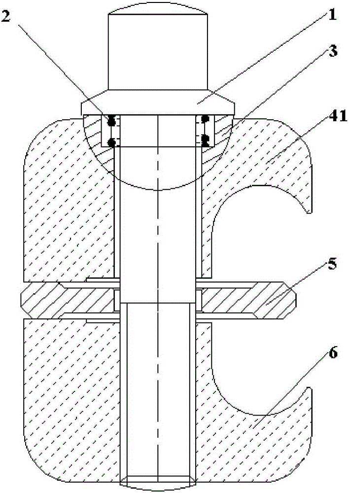
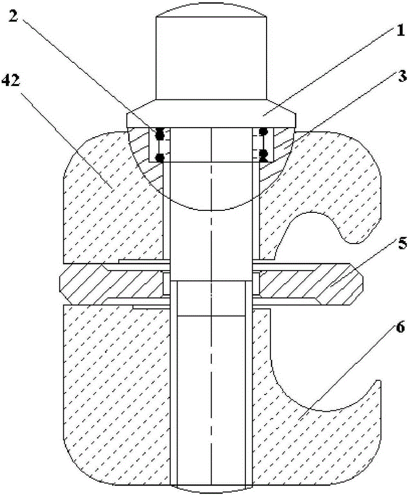
[0030] refer to figure 1 and figure 2 , the external fixed locking device described in this embodiment, the device includes: bolt 1, spring 2, ball pad 3, top piece, middle piece 5 and lock tube bottom piece 6; the top piece is the lock tube top piece 41 or lock pin Top sheet 42; the spring 2, the ball pad 3, the top sheet 4, the middle sheet 5 and the tube lock bottom sheet 6 are penetrated onto the screw rod of the bolt 1 in turn, and the spring 2 , the axes of the ball pad 3, the top sheet 4, the middle sheet 5, the bottom sheet 6 and the bolt 1 are coincident; through the connection of the screw rod 1 and the tube locking bottom sheet 6, the The spring 2 , the ball pad 3 , the top piece, the middle piece 5 and the lock tube bottom piece 6 are fixed sequentially, wherein the spring 2 is arranged close to the bolt cap of the bolt 1 . A more detailed explanation is as follows:

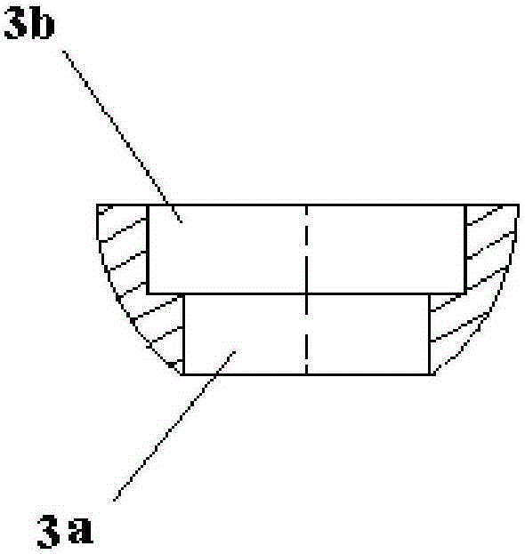
[0031] (1) If image 3 As shown, the ball pad 3 is a hemisphere whose upper and lower bottom ...


PUM


Abstract

The invention discloses a locking device for external fixation, and relates to the field of medical equipment. The locking device for external fixation is characterized by comprising a bolt, springs, a ball cushion, a top sheet, a middle sheet and a lock tube bottom sheet; the top sheet is a lock tube top sheet or a lock needle top sheet; the springs, the ball cushion, the top sheet, the middle sheet and the lock tube bottom sheet sequentially pass through a screw of the bolt, and the respective axes of the spring, the ball cushion, the top sheet, the middle sheet and the bottom sheet coincide with the axis of the bolt; and through connection of the bolt with the lock tube bottom sheet, the spring, the ball cushion, the top sheet, the middle sheet and the lock tube bottom sheet are fixed in sequence, wherein the springs are arranged close to the cap of the bolt. According to the invention, bending deformation of the bolt is reduced, steel needle deformation caused by internal stress from shifting of the steel needles is reduced, needle threading angles are not restricted, and internal stress is reduced.

Description

technical field [0001] The invention relates to the field of medical equipment, in particular to an external fixation locking device. Background technique [0002] The existing locking pin (tube) clamp for external fixation includes a pin clamp and a tube clamp connected in series on the fastening bolt, and its working principle is to loosen the fastening bolt to a preset target distance so that Press the rod and the needle into the rod groove and the needle groove of the locking needle (tube) clamp, then tighten the fastening bolts so that the rod and the needle maintain the required positional relationship during the operation, and then perform the fixation operation. But there are following deficiencies in the existing locking pin (pipe) clip: [0003] 1. Since the needle groove is used for multiple purposes, the diameter of the steel needle is different during the operation. When the steel needle is pressed in, the top plate of the locking needle is lifted up at a diffe...

Claims


Application Information

Patent Timeline
Patent Type & Authority Applications(China)
IPC IPC(8): A61B17/60
CPCA61B17/60A61B2017/606A61B2017/564A61B17/6466A61B2017/00477
Inventor 马克
Owner 马克
Why Eureka
Try Eureka