Stereo type flat plate antenna

A flat panel antenna, three-dimensional technology, applied in the direction of antennas, electrical components, etc., can solve the problems of inconvenience, general products have no structure, easy to receive noise and noise, etc.

Inactive Publication Date: 2007-10-10
ARCADYAN
View PDF0 Cites 6 Cited by
  • Summary
  • Abstract
  • Description
  • Claims
  • Application Information

AI Technical Summary

Problems solved by technology

[0004] Current antennas can be roughly divided into two types: omnidirectional antennas and directional antennas. Among them, omnidirectional antennas have a wider angle of receiving and transmitting signals, but are also more likely to receive noise and noise when receiving signals; and The power gain of the directional antenna is higher, and compared with the omnidirectional antenna, the received noise and noise are smaller, but the angle of the transmitted signal is narrower
In addition, regardless of whether it is an omnidirectional antenna or a directional antenna, the radiation pattern is fixed after the antenna design is completed, and the use

Method used


Image

  • Stereo type flat plate antenna
  • Stereo type flat plate antenna
  • Stereo type flat plate antenna

Examples


Embodiment Construction

[0058] For further elaborating the technical means and effects that the present invention adopts for reaching the intended purpose of the invention, below in conjunction with the drawings and preferred embodiments, the specific implementation, structure, features and effects of the three-dimensional panel antenna proposed according to the present invention will be described below. , as detailed below.

[0059] The three-dimensional panel antenna according to the preferred embodiment of the present invention will be described in detail below with reference to related drawings, wherein the same components will be described with the same reference symbols.

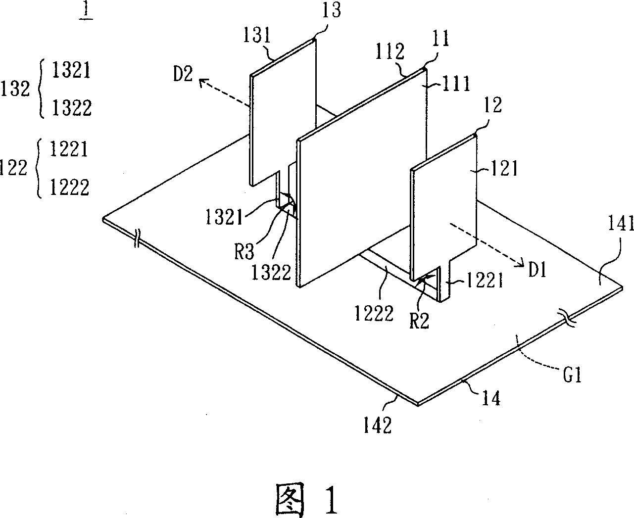
[0060] Please refer to FIG. 1 , which is a schematic perspective view of a three-dimensional panel antenna according to the first preferred embodiment of the present invention. The three-dimensional panel antenna 1 of the first preferred embodiment of the present invention includes a reflection unit 11, A first radiation unit...


PUM


Abstract

The stereotype tabulate antenna includes a reflection unit, a first radiating element (RE), and a second RE. The reflection unit possesses a first reflection plane (RP), and a second RP. Being setup opposite to the first RP of the reflection unit, the first RE possesses a first radiation portion, and a first electrical connection portion. One end of the said first electrical connection portion is connected to the first radiation portion electrically, and the first radiation portion is parallel to the first RP approximately. Being setup opposite to the second RP of the reflection unit, the second RE possesses a second radiation portion, and a second electrical connection portion. The second radiation portion is parallel to the second RP approximately. One end of the second electrical connection portion is connected to the second radiation portion electrically, and the other end is connected to the other end of the first electrical connection portion.

Description

technical field [0001] The invention relates to an antenna, in particular to a three-dimensional planar antenna which can change the radiation pattern according to actual needs, has high power gain, low power loss and can reduce receiving noise. Background technique [0002] With the vigorous development of wireless transmission, various products and technologies applied to multi-frequency transmission are brought at the same time, so many new products will have the performance of wireless transmission, so as to meet the needs of consumers. The antenna is an important component used to transmit and receive electromagnetic wave energy in the wireless transmission system. If there is no antenna, the wireless transmission system will not be able to transmit and receive data. Therefore, the role of the antenna is an indispensable part for wireless transmission. [0003] In addition, choosing an appropriate antenna can not only help to match the appearance of the product and imp...

Claims


Application Information

Patent Timeline
IPC IPC(8): H01Q19/10H01Q19/185
Inventor 郑世杰
Owner ARCADYAN
Why Eureka
Try Eureka