Control method for reflux welding curve on surface sticking process rpoduction line

A surface mount process and reflow soldering technology, which is applied in the direction of assembling printed circuits, electrical components, electrical components, etc., can solve the problems of public reporting of unresearched results and achieve high reliability.

Inactive Publication Date: 2007-10-10
SHANGHAI JIAO TONG UNIV
View PDF0 Cites 24 Cited by
  • Summary
  • Abstract
  • Description
  • Claims
  • Application Information

AI Technical Summary

Problems solved by technology

[0008] At present, there is no public report on the research

Method used


Image

  • Control method for reflux welding curve on surface sticking process rpoduction line
  • Control method for reflux welding curve on surface sticking process rpoduction line
  • Control method for reflux welding curve on surface sticking process rpoduction line

Examples


Embodiment Construction

[0023] The technical solutions of the present invention will be further described below through specific embodiments and in conjunction with the accompanying drawings. Taking the realization of a target reflow curve in a full hot air multi-temperature reflow furnace as an example, the steps and methods of determining the thermal control parameters of the reflow furnace according to the reflow curve of a specific shape are described. details as follows:

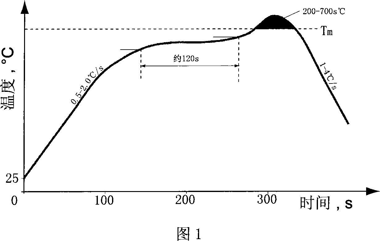
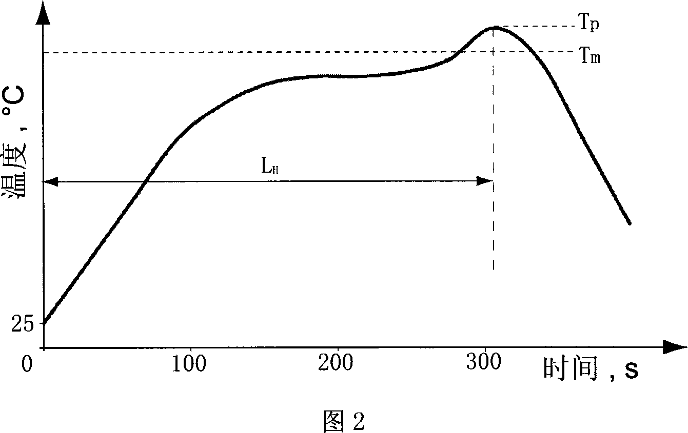
[0024] 1. A lead-free solder paste reflow profile recommended by the solder paste manufacturer, as shown in FIG. 1 , is used as the target profile in the embodiment of the present invention, and the heating factor is used to summarize the peak temperature and the liquid phase time. Using the total length of time it takes for the target curve to rise from room temperature to its peak temperature, L shown in Figure 2 H , divided by the total length of each heating zone of the reflow furnace used to obtain the running speed of t...


PUM


Abstract

The method comprises: the total temperature rise length of the target backflow curve is divided by the backflow oven heating length to get the belt speed of the oven; using each heating area length of the oven to divide the belt speed to get the stay time of the assembled electronic product in each heat area; according to the trace of the backflow curve, determining the temperature rise in the stay time of each heating area; using the temperature rise of the target backflow curve in each heating time interval as the difference value of each heating area temperature in backflow oven in order to set the heat source temperature parameters of each heat interval into a combined parameter; the combined parameters is represented by the temperature of the last heat area in adjacent cooling area, and is set at a temperature being 5-25deg.c higher than the peak temperature of the target backflow curve; the risen temperature value is adjusted based on the bounding point character; the temperature at cooling area can be set as 100-120deg.c lower than the fusion point of soldering past so as to get a complete control parameter setting of the backflow oven.

Description

technical field [0001] The invention relates to a method of how to control a reflow furnace with forced hot air convection as the main heat transfer mechanism on a surface mount process production line to realize reflow soldering between chip electronic components and printed circuit boards, and is especially suitable for reflow soldering with ball grid arrays. Various packaged chip components are reflow soldered on the same printed circuit board, and are suitable for lead-free soldering, which belongs to the technical field of microelectronic packaging. Background technique [0002] In the reflow soldering operation, the control of the reflow profile basically determines the success of the reflow soldering. The reflow profile is the profile that the solder joints between the SMD IC components and the printed circuit board should experience during the reflow soldering process. With the implementation of lead-free solder in the microelectronics manufacturing industry, the re...

Claims


Application Information

Patent Timeline
IPC IPC(8): H05K13/08H05K3/34
Inventor 高金刚吴懿平丁汉盛鑫军
Owner SHANGHAI JIAO TONG UNIV
Why Eureka
Try Eureka