
Eureka
For R&D, Eureka makes reading and utilizing patents & technical documents easy.
Eureka AIR
Designed for self-driven R&D workflows. Generate viable solutions, solve complex R&D challenges, empower your innovation with AI.

Eureka Materials
Designed for material experts only. Revolutionize your material R&D, from search, analyze, to developing new materials.

TechResearch
Generate reliable direction feasibility study reports for your R&D in just a few steps.

TechSeek
Discover and master advanced knowledge NOW. Basics, ideas, possibilities, all at once.

TechMind
As an expert in R&D Theories, TechMind can generates customized viable solutions instantly.

TechRisk
Analyze your overall solution with one click, know your potential R&D risks in advance.

TechMonitor
Get weekly tech updates, stay abreast of the latest tech innovations and key insights.
Method for detecting faucet of electronic jacquard machine and detection device using the same
An electronic jacquard and detection device technology, which is applied in the field of textile machinery, can solve the problems of inconvenient stitch expansion, low reliability, large sensor power consumption, etc., and achieves the effect that the detection device is simple, reliable and easy to expand.
- Summary
- Abstract
- Description
- Claims
- Application Information
AI Technical Summary
Problems solved by technology
Method used
Image

Examples
Embodiment 1
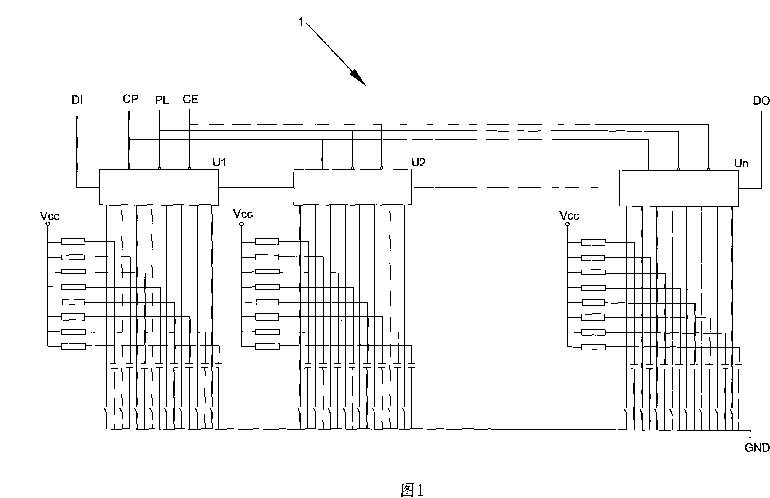
[0041] FIG. 1 is an electrical schematic diagram of the detection board of the present invention. The detection board 1 is provided with a plurality of parallel-in serial-out shift registers U1-Un and a plurality of detection switches. The parallel-in serial-out shift register is used to realize the function of the parallel-in serial-out sampler in the above-mentioned detection method, and each parallel-in serial-out register has an 8-bit parallel data input port, which can sample the detection switch in 8 positions , where DI is the serial data input line paralleled into the serial shift register, DO is the serial data output line paralleled into the serial shift register, PL is the parallel data latch line paralleled into the serial shift register, CP is the shift pulse clock line that is incorporated into the serial-out shift register, and CE is the shift pulse permission line that is incorporated into the serial-out shift register. Multiple parallel-in and serial-out shift r...
Embodiment 2
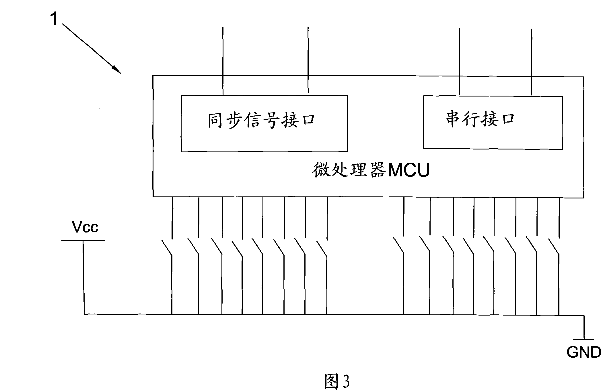
[0053] FIG. 3 is a block diagram of the electrical principle of the detection board 1 of this embodiment, which uses a microprocessor MCU as a sampler. The parallel input port of the microprocessor MCU is connected to a position detection switch. The structure of the detection switch is the same as that of the detection switch in Embodiment 1, and will not be repeated here. In addition, the microprocessor MCU is provided with two ports as synchronous signal interfaces, and the serial interface of the microprocessor MCU is used as serial data output. Usually the microprocessor MCU has more ports, but to reach the number of 80 detection switches on one detection board, it is not economical to use a large microprocessor MCU, so choose to use 2-4 smaller MCUs, This is more economical and easier to wire on the test board. Multi-chip MCU obtains the timing signal of each latitude through the synchronous signal interface to control synchronous sampling. Multi-chip MCUs pass the sam...
PUM
 Abstract
Description
Claims
Application Information
 - R&D Engineer
- R&D Manager
- IP Professional
- Industry Leading Data Capabilities
- Powerful AI technology
- Patent DNA Extraction
Browse by: Latest US Patents, China's latest patents, Technical Efficacy Thesaurus, Application Domain, Technology Topic, Popular Technical Reports.
© 2024 PatSnap. All rights reserved.Legal|Privacy policy|Modern Slavery Act Transparency Statement|Sitemap|About US| Contact US: help@patsnap.com