Heat pipe and its combining method with heat-conductive base

A heat pipe and bottom plate technology, which is applied in the field of combination of heat pipe and heat conduction base, can solve the problems of affecting heat transfer efficiency, tightness, insufficient tightness, etc.

Inactive Publication Date: 2007-10-17
陈世明 +1
View PDF0 Cites 5 Cited by
  • Summary
  • Abstract
  • Description
  • Claims
  • Application Information

AI Technical Summary

Problems solved by technology

[0008] Each of the above-mentioned patents utilizes grooves on the base to match a cladding plate (or fixed plate, etc.), or further uses a convex portion that can be bent and deformed by external force to press the cladding plate to clamp the cladding plate to combine th

Method used


Image

  • Heat pipe and its combining method with heat-conductive base
  • Heat pipe and its combining method with heat-conductive base
  • Heat pipe and its combining method with heat-conductive base

Examples


Embodiment Construction

[0041] The technical content and detailed description of the present invention are now described as follows in conjunction with the drawings:

[0042] Please refer to Figures 1 to 6, which are schematic diagrams of the process steps of an embodiment of the combination method of the heat pipe and the heat conduction base of the present invention and the combined structure of the heat sink, as shown in the figure: the heat pipe and the heat conduction base of the present invention A combination method, the steps of which at least include:

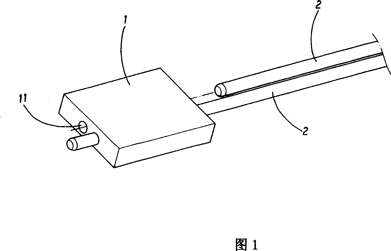
[0043] Step 1: Provide a heat-conducting bottom plate 1, at least one set of holes 11 is provided through its body, and the set of holes 11 is preferably biased against one surface side of the heat-conducting bottom plate 1, as shown in FIG. 1 ;

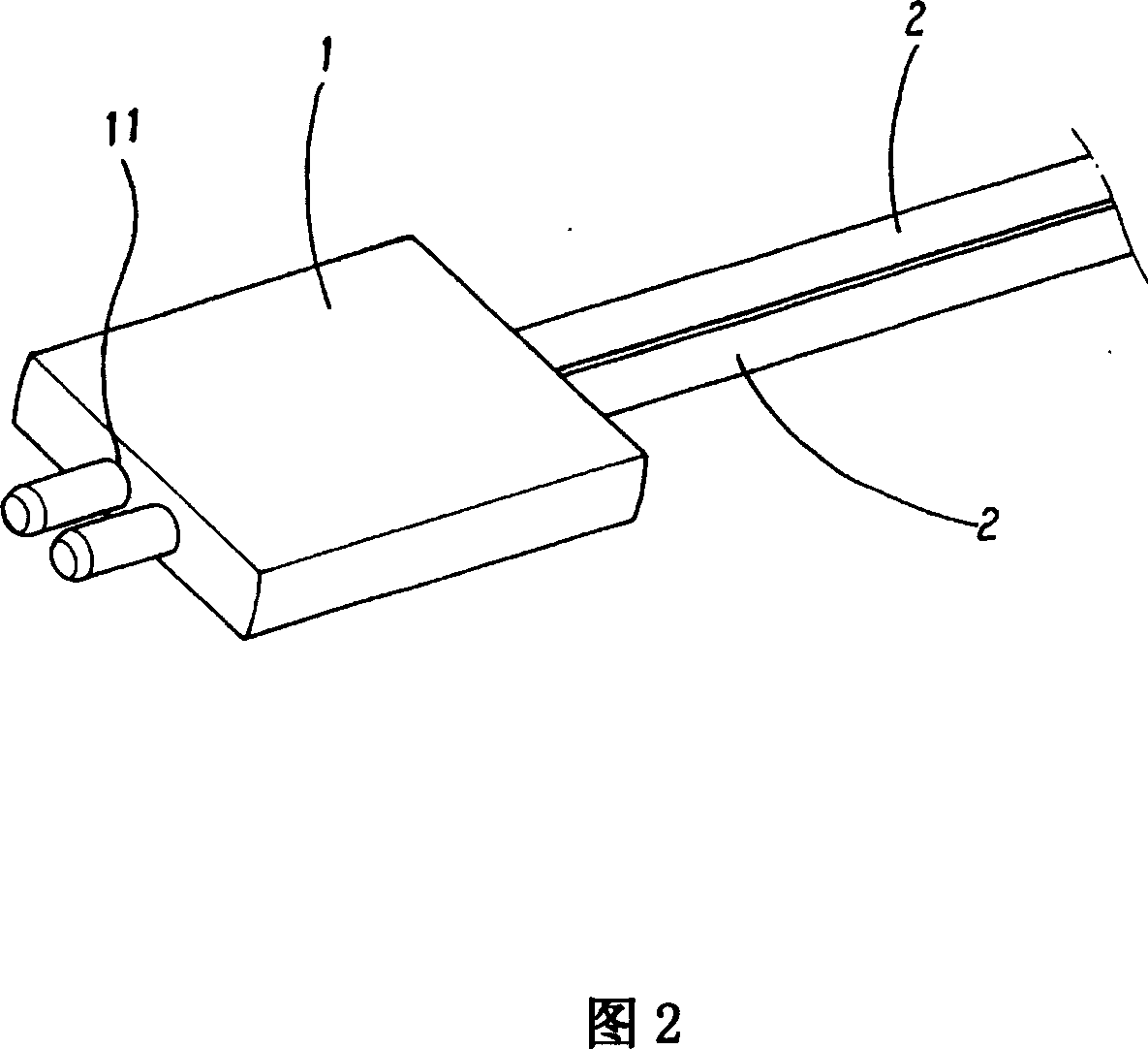
[0044] Step 2: Provide at least one heat pipe 2, and put each heat pipe 2 through the above-mentioned group of holes 11 respectively. As shown in FIG. Depending on requirements or designs;

[0045...


PUM


Abstract

A bonding method for heat conduction pipe and heat conduction base includes: through arranging at least a group of holes on a heat conduction substrate body, or any one of valley and protrusion formed opposite to the group holes for collocation on at least on surface thereof; penetrating most heat conduction pipes in the group holes; implementing urgent forming procedure, i.e. coupling a machining tool having at least a pressing piece and forcibly pressure exertion technology, exerting force to the surface of the heat conduction substrate, the valley or the protrusion to squeeze them to bond the heat conduction pipe and the heat conduction base, and then implementing a bending procedure, i.e. bending the heat conduction pipe for a predetermined angle for penetrating and bonding most radiation fins; finishing the radiation device and applying the same in radiation for electronic assembly heat bonding.

Description

technical field [0001] The present invention relates to a combination method of a heat pipe and a heat conduction base, especially a non-clamping type threading tight and seamless forming method that combines the heat pipe and the heat conduction base into one body, so as to improve the tightness of the combination and make it good rate, and make a heat sink with high bonding and heat transfer efficiency. Background technique [0002] It is known that the heat dissipation devices currently used in electronic components, especially the heat dissipation devices that require better heat dissipation efficiency, are all heat dissipation devices composed of heat pipes and heat dissipation fins to quickly transfer the heat generated by electronic components for large-area cooling. The heat dissipates, and the heat pipe is designed to meet the requirements of space configuration and the heat transfer efficiency of the better area. It also conducts heat quickly by combining a heat-co...

Claims


Application Information

Patent Timeline
IPC IPC(8): F28D15/02B23P15/26
Inventor 陈世明秦秋子
Owner 陈世明
Why Eureka
Try Eureka