
Infrared sensor switch

An infrared sensor and sensor technology, applied in the direction of electric switches, electronic switches, thermal switch components, etc., can solve the problems of not being able to detect the human body, and the central axis cannot be pointed forward.

Inactive Publication Date: 2007-10-17
MATSUSHITA DENKO KK
View PDF1 Cites 4 Cited by
  • Summary
  • Abstract
  • Description
  • Claims
  • Application Information

AI Technical Summary

Problems solved by technology

However, the central axis of the detection range is rotated upwards and downwards from the lower 45 degrees, and the central axis cannot point forward, so if the switch is installed at a position shorter than a person, the human body may not be detected

Method used


Image

  • Infrared sensor switch
  • Infrared sensor switch
  • Infrared sensor switch

Examples


Embodiment Construction

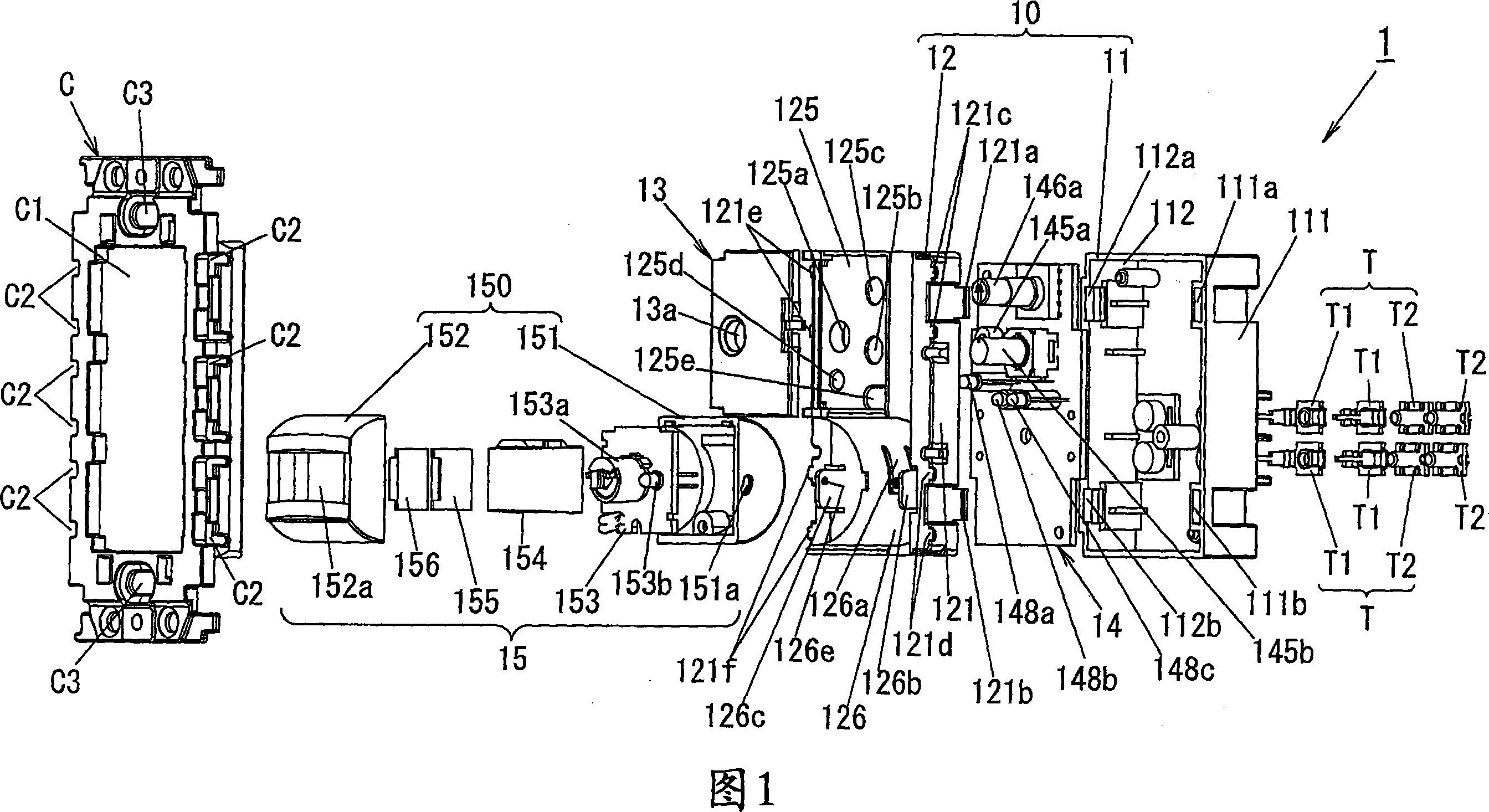
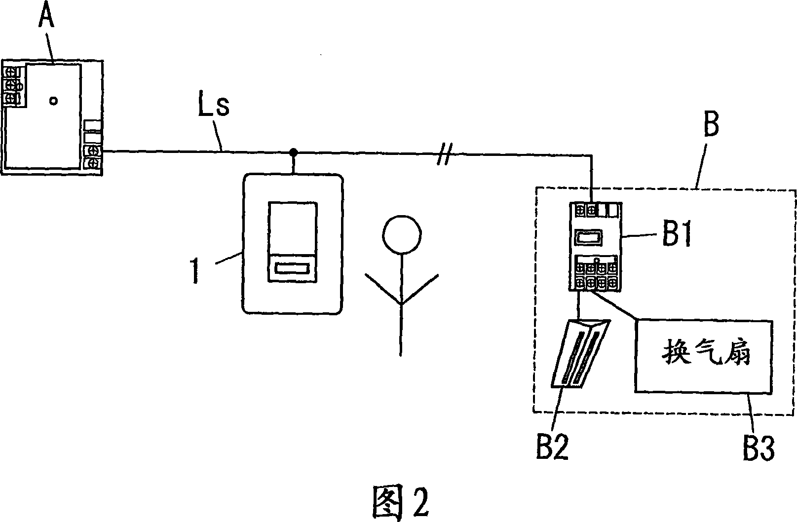
[0055] 1 and 2 show a first embodiment according to the present invention, namely an infrared sensor switch 1 . As shown in FIG. 2 , the switch 1 is connected to the main control unit A and the corresponding load unit B through a two-wire signal cable Ls. This system of Figure 2 is generally provided with a load cell (B) and a switch (1).

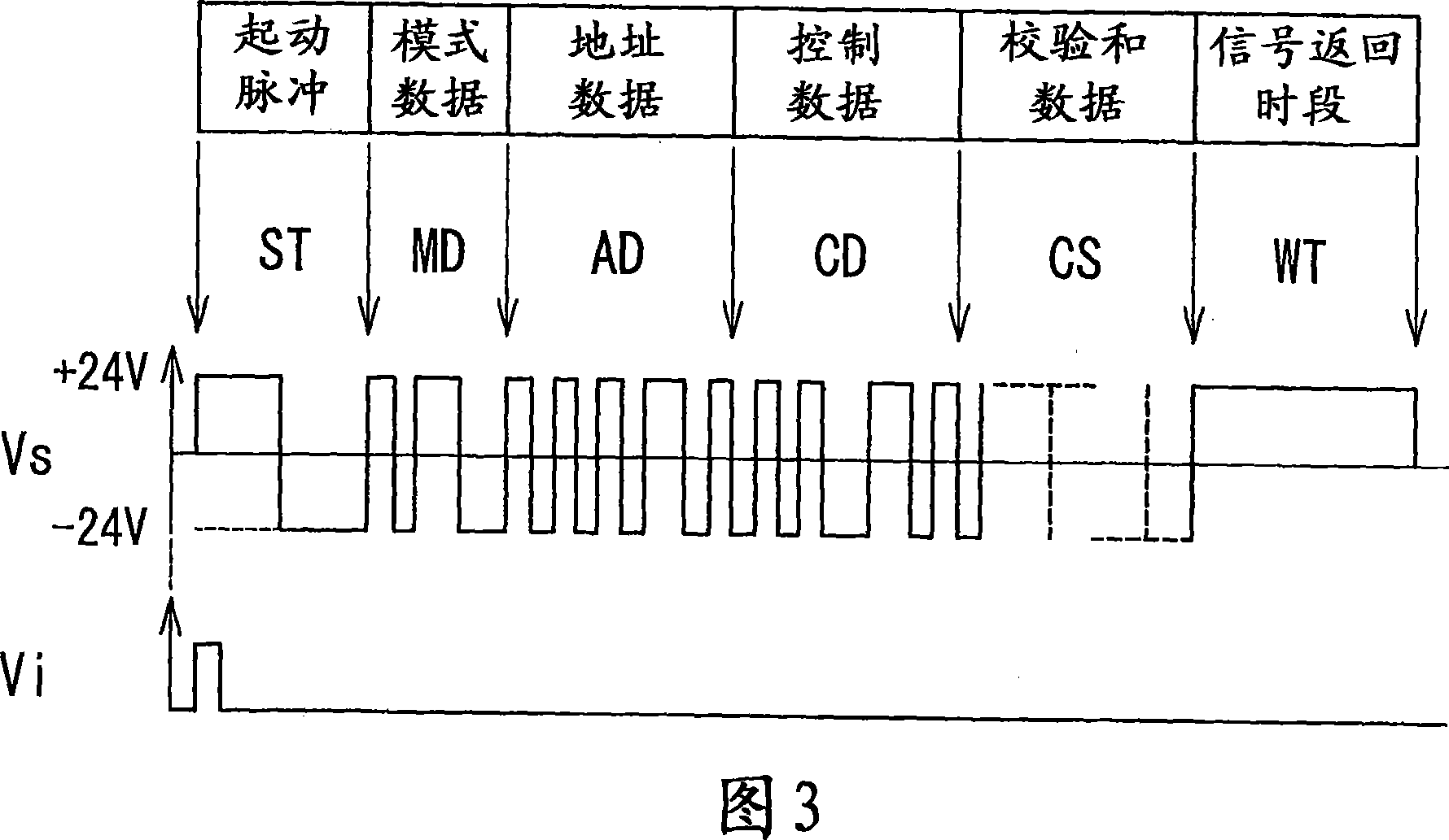
[0056] Unit A includes communication circuitry that acts as a transmitter and receiver. Based on time division multiplexing, the unit A sends out a transmission signal through the signal cable Ls, and sends information to and receives information from each unit B and each switch 1 through the transmission signal. As shown in FIG. 3, the transmission signal Vs is a time-division multiplexed signal, which is a bipolar signal of + / -24V and includes a start pulse ST, mode data MD, address data AD, control data CD, error correction code CS, and signal Return time period WT. The start pulse ST represents the beginning of the signal Vs. Mode d...


PUM


Abstract

An infrared sensor switch of the invention comprises an infrared sensor with a detection range, and a controller that uses the sensor to try to detect whether or not a person exists in the detection range and controls on and off of a corresponding load unit based on each detection result obtained from the sensor. The switch further comprises a sensor block provided with the sensor, and a housing that is put in a wall and retains the block so that the center axis of the detection range can be rotated about a horizontal axis and rotated up to at least 40 degrees downward from a forward direction of 0 degree.

Description

technical field [0001] The present invention generally relates to an infrared sensor switch, and more particularly relates to an infrared sensor that uses an infrared sensor to attempt to detect whether a person exists within the detection range of the sensor, and controls the corresponding load unit to be turned on and off based on the detection result. Sensor switch. Background technique [0002] This type of infrared sensor switch is installed, for example, on a ceiling, a wall, etc., so as to be used as an energy-saving unit. For example, a terminal unit described in Japanese Patent Application Publication No. H6-245282 published on September 2, 1994 is mounted on a wall. The unit includes a printed circuit board on which an infrared sensor is mounted, and a rotating frame holding the printed circuit board and rotating around a vertical axis by a direction adjustment knob. In the case of this unit, the central axis of the detection range of the infrared sensor can be r...

Claims


Application Information

Patent Timeline
Patent Type & Authority Applications(China)
IPC IPC(8): H01H37/02H01H35/00H04Q9/00H03K17/94
CPCG08B13/19H01H2239/07H05B37/0227Y02B20/44H05B47/13Y02B20/40H04Q9/00G08B13/189H04Q9/14
Inventor 松冈万纪子家城知大横田浩二薮肇中埜进三浦启
Owner MATSUSHITA DENKO KK
Learn More