
Eureka
For R&D, Eureka makes reading and utilizing patents & technical documents easy.
Eureka AIR
Designed for self-driven R&D workflows. Generate viable solutions, solve complex R&D challenges, empower your innovation with AI.

Eureka Materials
Designed for material experts only. Revolutionize your material R&D, from search, analyze, to developing new materials.

TechResearch
Generate reliable direction feasibility study reports for your R&D in just a few steps.

TechSeek
Discover and master advanced knowledge NOW. Basics, ideas, possibilities, all at once.

TechMind
As an expert in R&D Theories, TechMind can generates customized viable solutions instantly.

TechRisk
Analyze your overall solution with one click, know your potential R&D risks in advance.

TechMonitor
Get weekly tech updates, stay abreast of the latest tech innovations and key insights.
A high power high-precision power supply device
A power supply device, high-precision technology, applied in the direction of output power conversion device, negative feedback circuit layout, AC power input conversion to DC power output, etc., can solve the problems of large power supply current output and difficult technology implementation
- Summary
- Abstract
- Description
- Claims
- Application Information
AI Technical Summary
Problems solved by technology
Method used
Image

Examples
Embodiment Construction
[0016] The present invention will be specifically described below in conjunction with the accompanying drawings and specific embodiments.
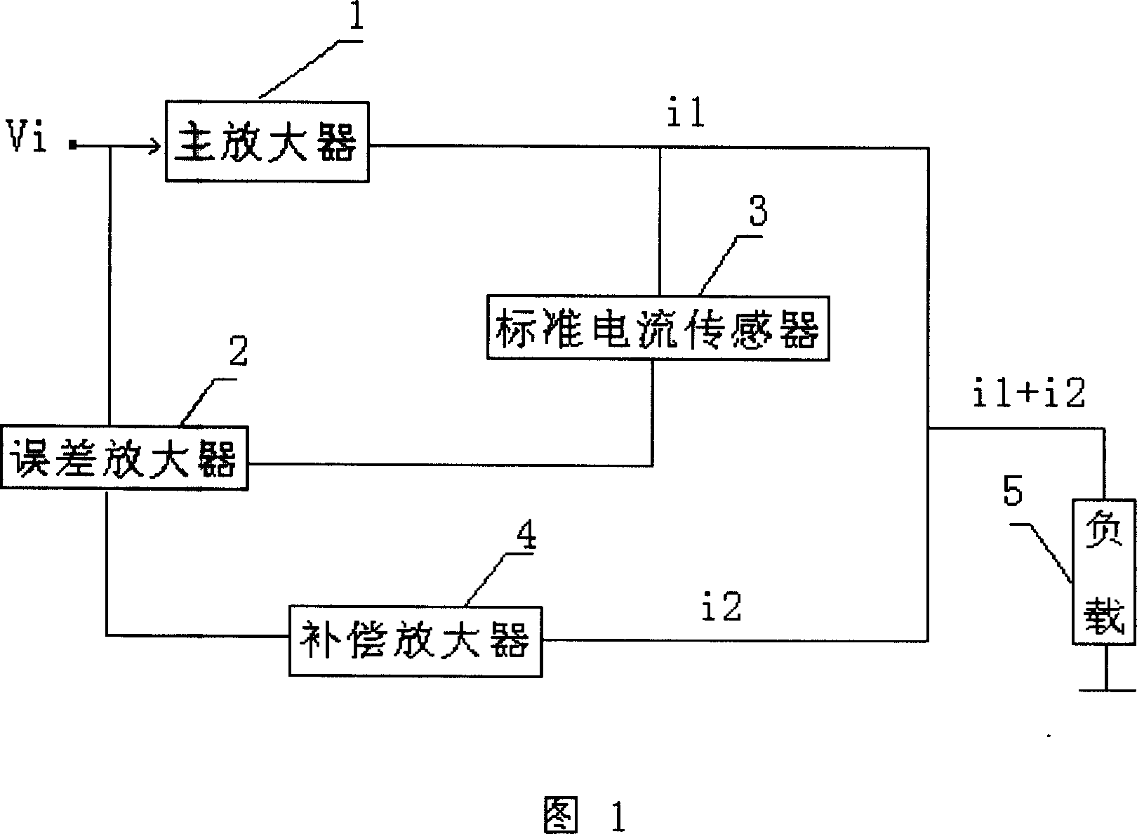
[0017] Shown in accompanying drawing 1, is the general circuit structure diagram of high-power high-precision power supply device, is made up of main amplifier (1), compensation amplifier (4), load (5), error amplifier (2) and current sensor (3). The main amplifier is composed of multiple power units connected in parallel. By inputting a given signal Vi, the main amplifier outputs current i1, which is sampled by a standard current sensor and compared with the given signal to obtain an error. After being amplified by the error amplifier, it is used as the compensation amplifier. Input, compensate the amplifier output current i2, so the sum of i1 and i2 is the actual load current.
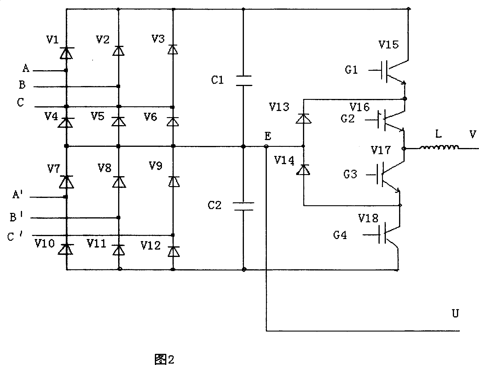
[0018] Attached Figure 2 is the circuit diagram of the unit in the main amplifier. The rectifier is composed of two sets of three-phase uncontrolled full bridges...
PUM
 Abstract
Description
Claims
Application Information
 - R&D Engineer
- R&D Manager
- IP Professional
- Industry Leading Data Capabilities
- Powerful AI technology
- Patent DNA Extraction
Browse by: Latest US Patents, China's latest patents, Technical Efficacy Thesaurus, Application Domain, Technology Topic, Popular Technical Reports.
© 2024 PatSnap. All rights reserved.Legal|Privacy policy|Modern Slavery Act Transparency Statement|Sitemap|About US| Contact US: help@patsnap.com