Blowing or sucking type air compressor cascade experiment system

An experimental system and compressor technology, which is applied in the direction of liquid variable displacement machinery, mechanical equipment, machines/engines, etc., can solve the problems of inability to test the internal flow of air-blowing or air-breathing compressor cascades, and achieve easy detailed measurement , increase the blade load, and the effect of low experimental cost

Inactive Publication Date: 2007-10-24
HARBIN INST OF TECH
View PDF0 Cites 25 Cited by
  • Summary
  • Abstract
  • Description
  • Claims
  • Application Information

AI Technical Summary

Problems solved by technology

[0003] In order to solve the problem that the existing compressor cascade test device cannot test the internal flow of the air blowing or suction type compressor cascade, the present invention further provides an experimental system for the air blowing or air suction type compressor cascade

Method used


Image

  • Blowing or sucking type air compressor cascade experiment system
  • Blowing or sucking type air compressor cascade experiment system
  • Blowing or sucking type air compressor cascade experiment system

Examples


specific Embodiment approach 1

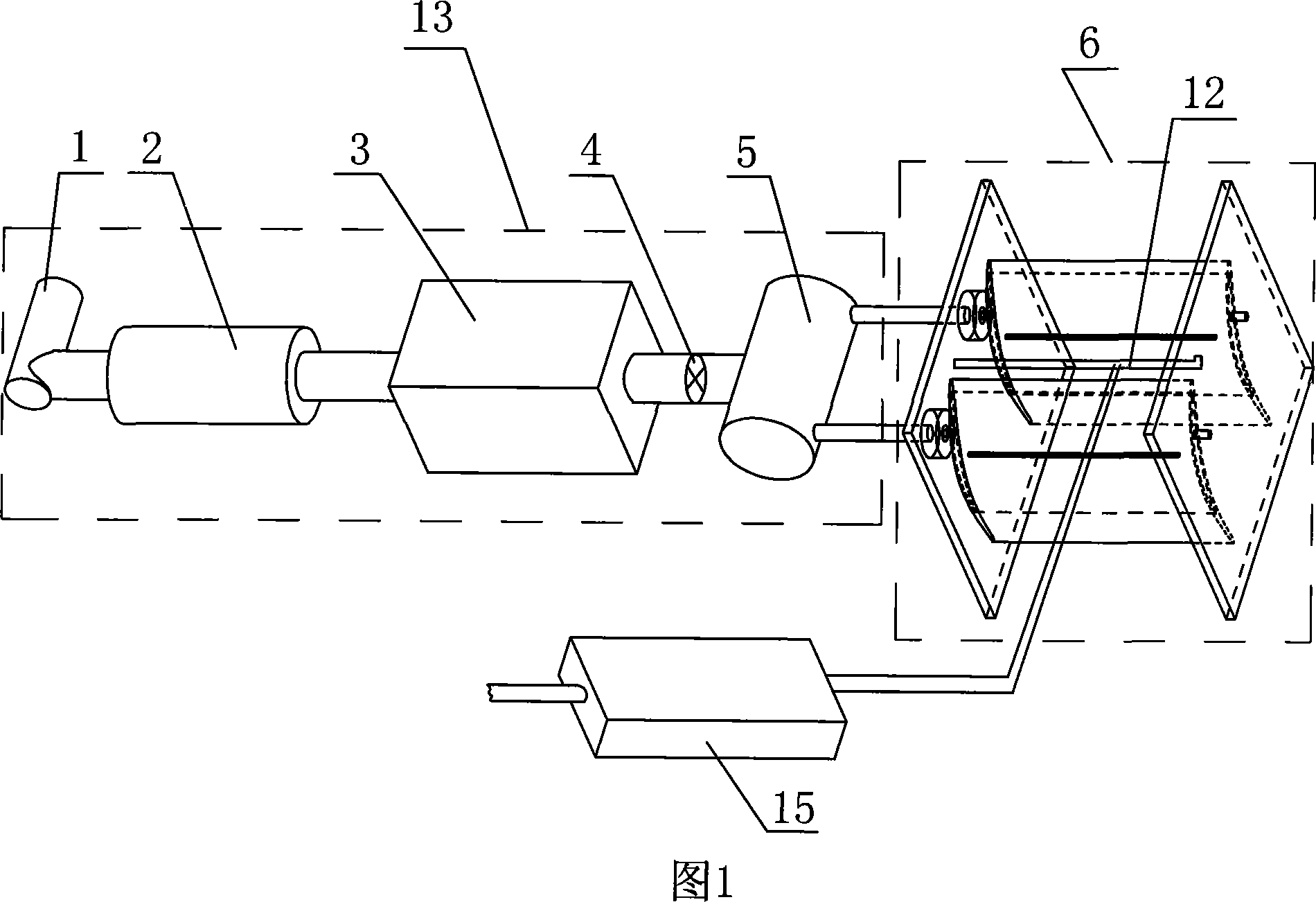
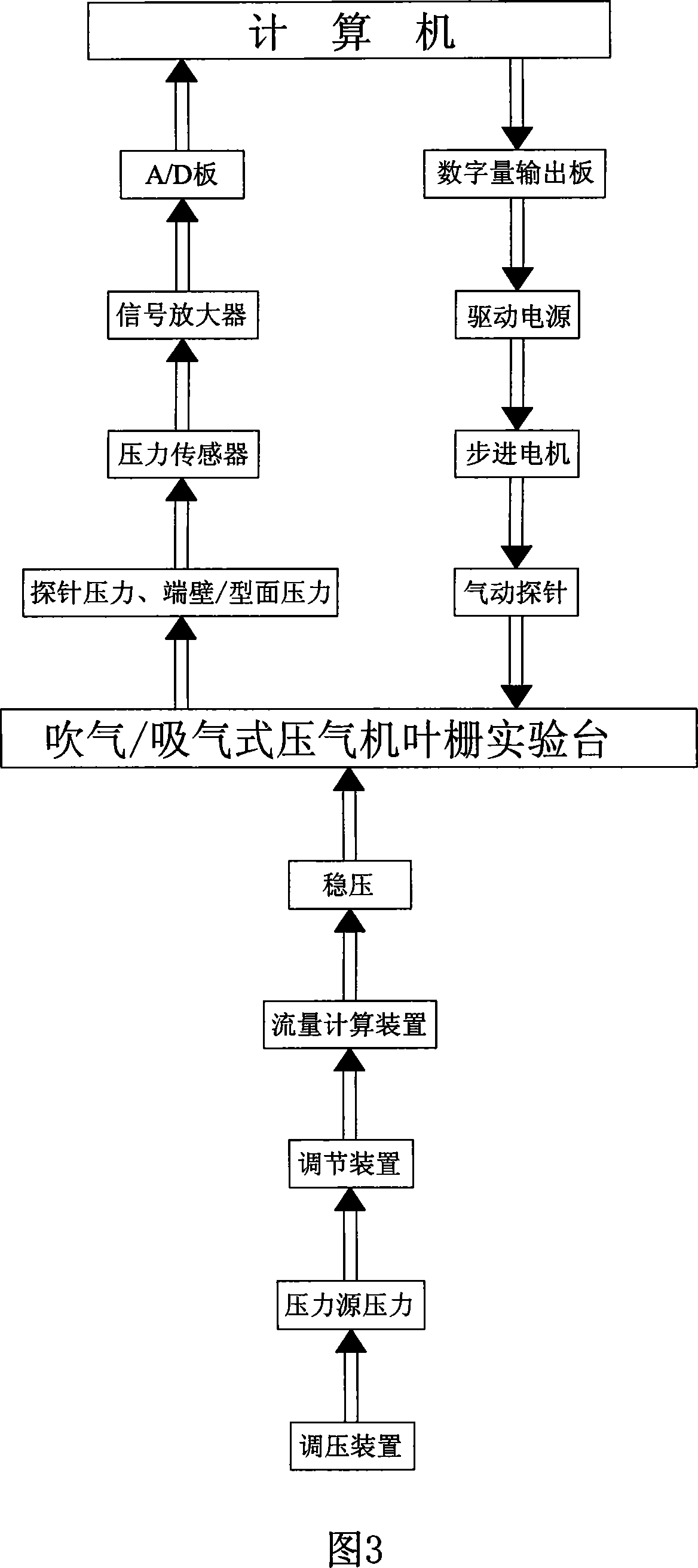
[0007] Embodiment 1: As shown in FIG. 1 and FIG. 2 , the air blowing or air suction compressor cascade experimental system of this embodiment is composed of an air blowing / suction device 13 and a plane cascade experimental device 6. The described The air blowing / suction device 13 is communicated with the plane cascade experimental device 6, and the plane cascade experimental device 6 consists of an upper end plate 7, a lower end plate 8, a solid blade 9, a hollow blade 10, and an upper air blowing / suction interface 11. -1. The lower blowing / suction interface 11-2 and the probe 12 are composed. The left and right ends between the upper end plate 7 and the lower end plate 8 are provided with at least one solid blade 9. The solid blade At least three hollow blades 10 are arranged between the upper end plate 7 and the lower end plate 8 on the inner side; the upper air blowing / suction interface 11-1 is respectively arranged on the upper end cross section of each hollow blade 10, and...

specific Embodiment approach 2

[0008] Embodiment 2: As shown in FIG. 1 , the air blowing / suction device 13 described in this embodiment is composed of an air blowing / suction pressure source 1, a primary pressure stabilization tank 2, a flow measurement device 3, a regulating valve 4 and a second The secondary surge tank 5 is composed of the air blowing / suction pressure source 1, the secondary surge tank 2, the flow metering device 3, the regulating valve 4 and the secondary surge tank 5 from left to right and connected in series. At the same time, the secondary surge tank 5 is connected with the plane cascade experimental device 6 . The primary surge tank 2 and the secondary surge tank 5 stabilize the pressure and ensure the equal and uniform pressure inside the air blowing / suction blade cavity. The regulating valve 4 and the flow metering device 3 are used to adjust and accurately measure the air blow / Suction flow, blow / suction pressure source 1 is used to provide back pressure, when blowing, blow / suction...

specific Embodiment approach 3

[0009] Embodiment 3: As shown in FIG. 2 , the suction surface of the hollow blade (10) according to this embodiment is provided with an air blowing / suction groove 14. The flow in the channel composed of adjacent blades is periodic, and it is only necessary to measure the flow in one channel in the middle of the cascade. Therefore, only the three middle blades are provided with air blowing / suction channels, and other blades do not need special processing , reducing the experimental cost. When the pressure of the pressure source is higher than the pressure at the position where the air blowing / suction channel is opened on the surface of the blade or end wall, the low-energy fluid is blown out, otherwise, the low-energy fluid is sucked out. Other components and connection relationships are the same as in the first or third embodiment.


PUM


Abstract

Air-blowing or air-breathing compressor cascade experimental system relates to an experimental installation of testing compressor cascade. The present invention solves the problem of prior test equipment can not test inner flowing in air-blowing or air-breathing compressor cascade. The right and left two ends between said top plate (7) and bottom plate (8) are equipped with at least one solid blade (9) separately, three hollow blades (10) are installed between the top plate (7) and the bottom plate (8) in said solid blade (9), said upper Air-blowing/air-breathing interface (11-1) are installed on the top horizontal section of each hollow blades (10), said lower Air-blowing/air-breathing interface (11-2) are installed on the bottom horizontal section of each hollow blades (10), said probe (12) is installed between the top plate (7) and the bottom plate (8). The invention can be considered as the simplified model of carefully analysis of three-dimensional flow field structure and the aerodynamic performance in compressor cascade, it is the effective approach of the searching of compressor performance improvements.

Description

technical field [0001] The invention relates to an experimental system for testing compressor blade cascades. Background technique [0002] Axial flow compressor is an important part of gas turbine, which can compress gas to a specific pressure. It is widely used in aviation, ground, ships and missiles and other fields. It is an important power system. The blade is the main part of the compressor. When the gas flows through the flow channel composed of the blade, it is subjected to the force of the blade and obtains mechanical energy. Modern gas turbines place high demands on the load level of its main component, the compressor, and the large increase in blade load will cause the transverse pressure gradient in the cascade (two or more blades are called cascades) and The secondary flow is strengthened, the boundary layer is thickened and large-scale unsteady flow separation occurs, the cascade loss increases rapidly, and the compressor stall margin and efficiency drop sharp...

Claims


Application Information

Patent Timeline
Patent Type & Authority Applications(China)
IPC IPC(8): F04B51/00
Inventor 陈浮宋彦萍陈绍文陆华伟
Owner HARBIN INST OF TECH
Why Eureka
Try Eureka