Fiber supply device of automatic optical fiber winding machine

An optical fiber winding machine and automatic technology, applied in the direction of light guides, optics, optical components, etc., can solve the problems such as the inability to guarantee the winding quality, and achieve the effects of improving tension control accuracy, improving stability, and low friction

Inactive Publication Date: 2007-10-24
BEIHANG UNIV
View PDF0 Cites 2 Cited by
  • Summary
  • Abstract
  • Description
  • Claims
  • Application Information

AI Technical Summary

Problems solved by technology

How to wind a high-quality fiber optic ring is very important to the development of fiber optic gyroscopes. There are many winding methods, and the quadrupole symmetrical winding method has the best effect, which is a method commonly used in the world. Manual winding is adopted, and there is no special equipment, so the winding quality cannot be guaranteed

Method used


Image

  • Fiber supply device of automatic optical fiber winding machine
  • Fiber supply device of automatic optical fiber winding machine
  • Fiber supply device of automatic optical fiber winding machine

Examples


Embodiment Construction

[0024] The present invention will be further described in detail below in conjunction with the accompanying drawings.

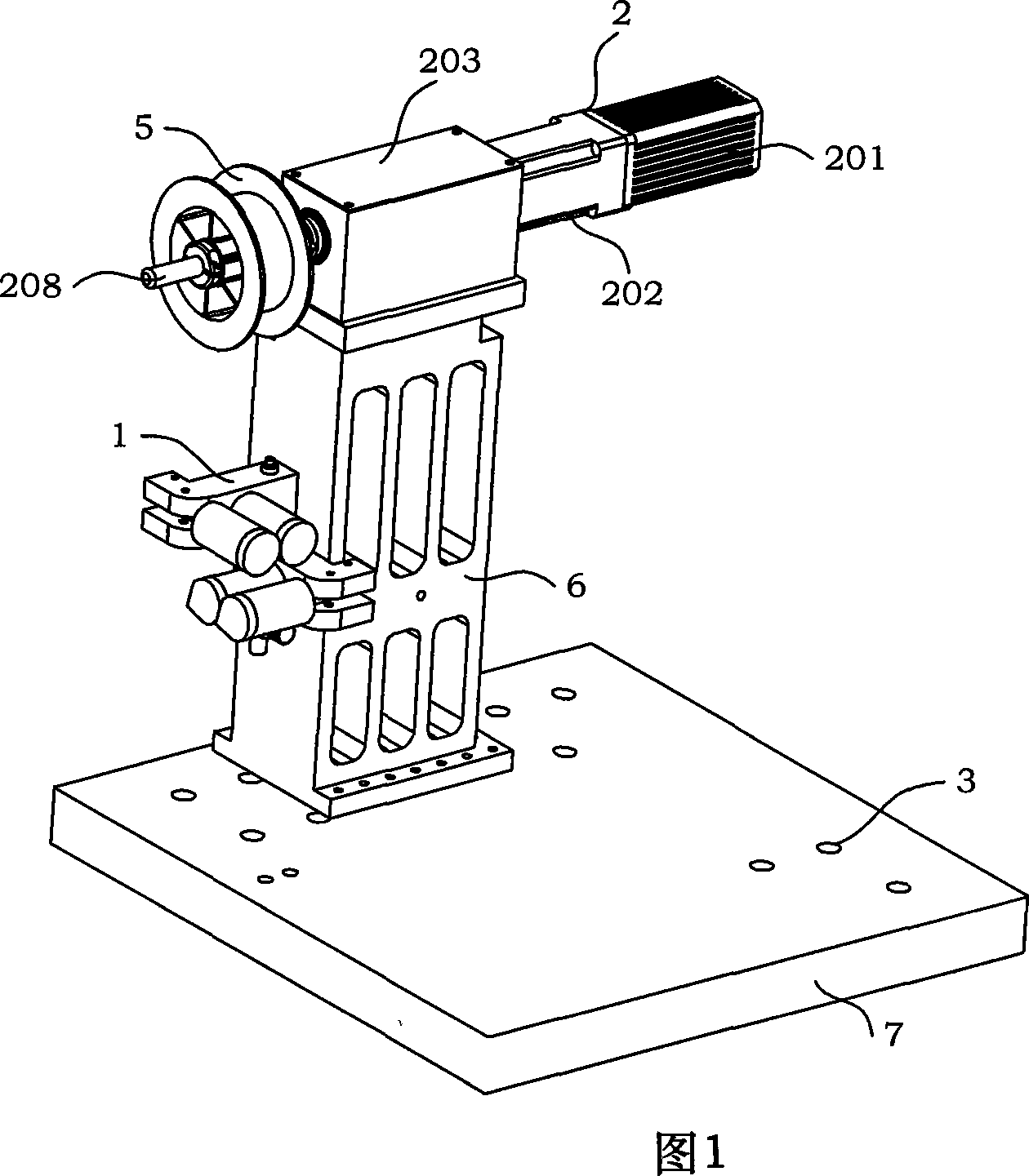
[0025] Please refer to Fig. 1, the present invention is a fiber feeding mechanism suitable for automatic optical fiber winding machines, the fiber feeding mechanism consists of an optical fiber convergence assembly 1, a drive assembly 2, a transmission box 4, a fiber pay-off wheel 5, and a support seat 6 and the slide table 7, the lower end of the support seat 6 is mounted on the slide table 7 through the cooperation of screws and nuts; the upper end of the support seat 6 is equipped with a transmission box 4; the drive assembly 2 is installed on the transmission box 4, and the motor 201 1. The reducer 202 is placed on the outer rear side of the transmission box body 4, and the precision main shaft 208 of the drive assembly 2 is suspended on the outer front side of the transmission box body 4; the fiber unwinding wheel 5 is installed on the precision main shaf...


PUM


Abstract

The invention discloses a fiber feeder used in automatic fiber coiler, composed of a fiber collector, a driver, a transmit box, a fiber discharge wheel, a support base, and a sliding table, wherein the support base is mounted on the sliding table, while the upper end is mounted with the transmit box, the driver is on the transmit box, while a motor and a speed reducer are mounted at the outer back of the transmit box, the accurate shaft of the driver is suspended at the outer front of the transmit box, which is mounted with the fiber discharge wheel, the fiber collector is at one side of the support base, vertically with the fiber discharge wheel. The invention can feed fiber in various automatic fiber coilers, and in the machine as fiber repeat coiler and fiber selector. The invention uses the accurate suspended shaft to vertically support the fiber discharge wheel to discharge fiber, and arranges the fiber collector under the wheel to collect the fiber output by the wheel into a fixed point to be moved out, thereby confirming the feeding direction consistence of the tension wheel and confirming the tension consistence in the fiber coiling process.

Description

technical field [0001] The invention relates to a fiber feeding mechanism of an automatic optical fiber looping machine. Background technique [0002] The fiber optic gyroscope was born in 1976. It is a new type of sensor that uses fiber optic sensing technology to measure the space inertial rotation rate. It has developed into a new mainstream instrument with epoch-making characteristics in the field of inertial technology. Compared with the laser gyroscope, it has higher precision, low cost, small size and light weight. The application prospect of fiber optic gyroscope is very broad. It is not only used for aircraft and ship navigation, missile guidance, and high-precision position control of spacecraft, but also can be used for civilian use in the guidance of high-end cars, as well as robots and automatic control systems, etc. . [0003] The fiber optic ring is the sensing core of the fiber optic gyroscope, and its basic requirements are a large extinction ratio and goo...

Claims


Application Information

Patent Timeline
Patent Type & Authority Applications(China)
IPC IPC(8): G02B6/00B65H59/38G01C19/72
Inventor 董全林张春熹杨德伟王夏宵姜长星韩敏
Owner BEIHANG UNIV
Why Eureka
Try Eureka