Radio communication apparatus
A technology of wireless communication device and metering device, which is applied in the direction of selection device, remote measurement/remote control selection device, radio/inductive link selection arrangement, etc., which can solve the problem that power consumption is not effectively reduced, circuits that do not need to be operated are not considered, and there is no need to operate Problems such as radio signal circuit blocks to achieve low power consumption and prolong battery life
- Summary
- Abstract
- Description
- Claims
- Application Information
AI Technical Summary
Problems solved by technology
Method used
Image
Examples
Embodiment 1
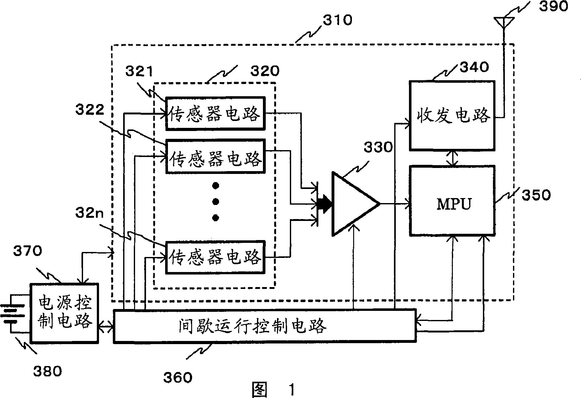
[0021] FIG. 1 is a block diagram of a wireless communication device including an intermittent operation control circuit of the present invention.
[0022] The wireless communication device is composed of a wireless sensor network system unit 310 , an intermittent operation control circuit 360 , a power supply control circuit 370 , a battery 380 , and an antenna 390 . The wireless sensor network system unit 310 is composed of a sensor circuit unit 320 , an analog-to-digital converter (ADC) 330 , a transceiver circuit 340 , and an MPU 350 . The sensor circuit part 320 has several sensor circuits 321-32n, and these sensor circuits include various environmental observation functions for observing natural environments such as air temperature, room temperature, humidity, and sunlight. The function of the output after the electrical signal.
[0023] The ADC 330 converts the analog electrical signals output by the sensor circuits 321 to 32n including various environmental observation...
Embodiment 2
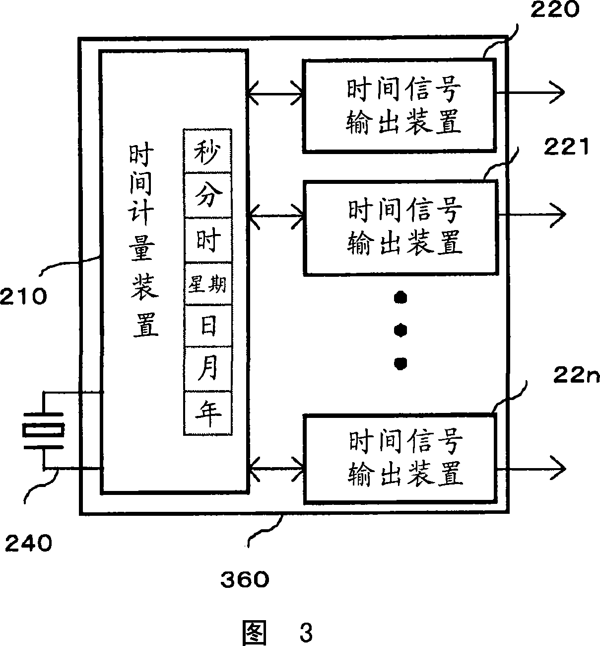
[0032] Fig. 3 is a block diagram of an intermittent operation control circuit of a second embodiment of the present invention. The intermittent operation control circuit 360 is composed of the time measuring device 210 , the time signal output devices 220 to 22n, and the crystal oscillator 240 . The time measuring device 210 can pre-arbitrarily set a time interval or elapsed time in units of any one of year, month, day, week, hour, minute, and second according to the function of the real-time clock. The time signal output devices 220 to 22n output inverted signals after a time interval or elapsed time arbitrarily set in advance by the time measuring device 210 .
Embodiment 3
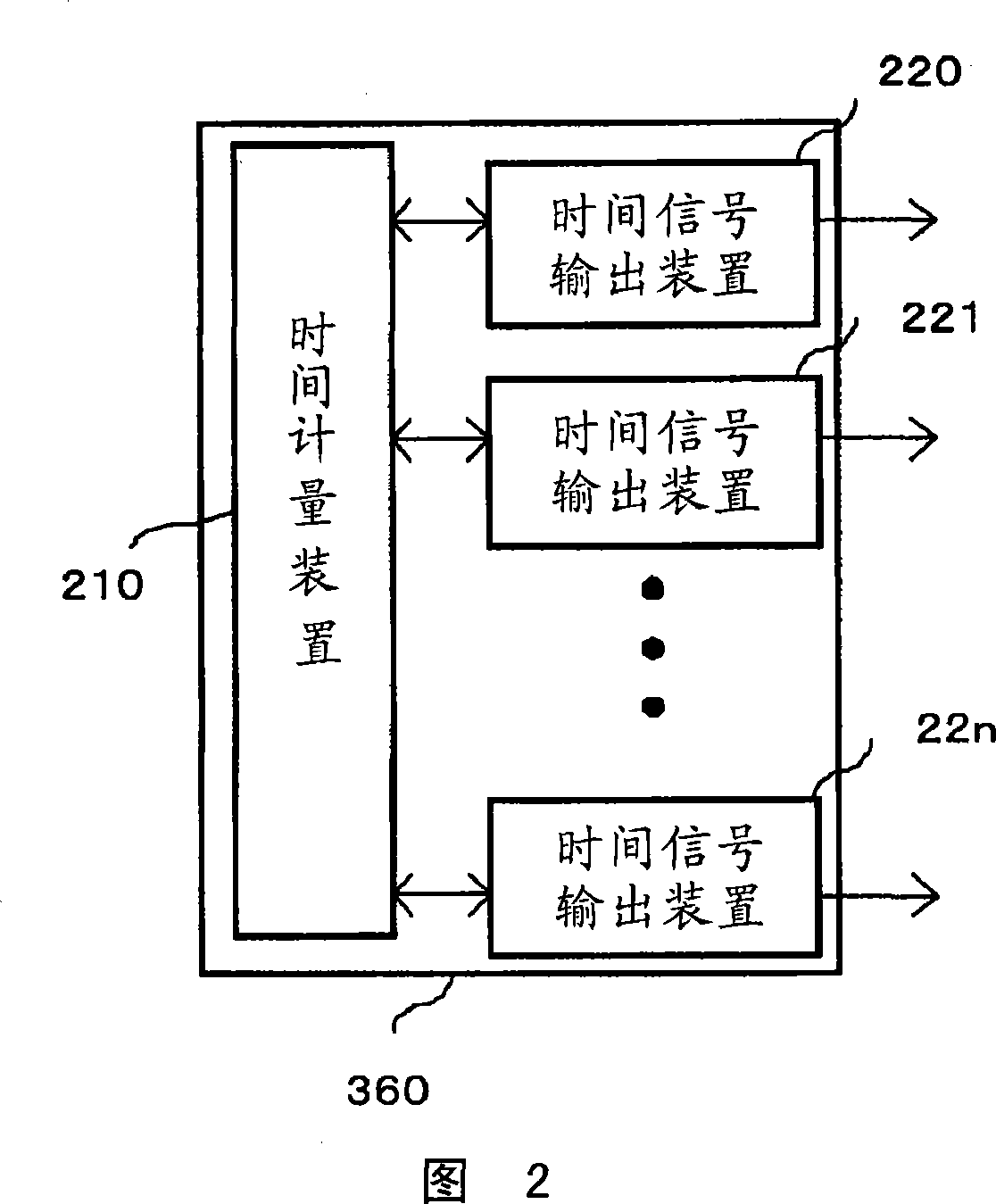
[0034] 4 and 5 are block diagrams of the intermittent operation control circuit of the third embodiment of the present invention. Different from the intermittent operation control circuit shown in FIG. 2 and FIG. 3 , it includes a serial data input and output device 250 .
[0035] Since the serial data input / output device 250 is included, the time interval or elapsed time of the time measuring device 210 can be arbitrarily set from the outside by transmitting data to the serial data input / output device 250 . In addition, the serial data input / output device 250 has a function of notifying the time interval or elapsed time measured by the time measuring device 210 to the outside.
[0036] The time signal output devices 220 to 22n output inverted signals at a time interval or elapsed time arbitrarily set by the time measuring device 210 .
[0037] As described above, since the function of controlling independent arbitrary time intervals or elapsed times of a plurality of time si...
PUM
 Abstract
Description
Claims
Application Information
 - R&D
- Intellectual Property
- Life Sciences
- Materials
- Tech Scout
- Unparalleled Data Quality
- Higher Quality Content
- 60% Fewer Hallucinations
Browse by: Latest US Patents, China's latest patents, Technical Efficacy Thesaurus, Application Domain, Technology Topic, Popular Technical Reports.
© 2025 PatSnap. All rights reserved.Legal|Privacy policy|Modern Slavery Act Transparency Statement|Sitemap|About US| Contact US: help@patsnap.com


