
Manufacturing facility and super finishing apparatus for ball bearing

A technology for ball bearings and manufacturing equipment, applied in the direction of superfinishing machines, manufacturing tools, ball bearings, etc., to achieve the effect of improving dimensional accuracy and shape accuracy, and improving the rate of results

Inactive Publication Date: 2007-10-24
NSK LTD
View PDF5 Cites 8 Cited by
  • Summary
  • Abstract
  • Description
  • Claims
  • Application Information

AI Technical Summary

Problems solved by technology

[0022] Due to these matters, the inventors of the present invention consider that it is not sufficient to consider only the amount of change in the diameter machining target value of the outer ring raceway 4 or the inner ring raceway 5 to the grinding processing device in order to improve the result rate of the assembly process.

Method used


Image

  • Manufacturing facility and super finishing apparatus for ball bearing
  • Manufacturing facility and super finishing apparatus for ball bearing
  • Manufacturing facility and super finishing apparatus for ball bearing

Examples


Embodiment 1

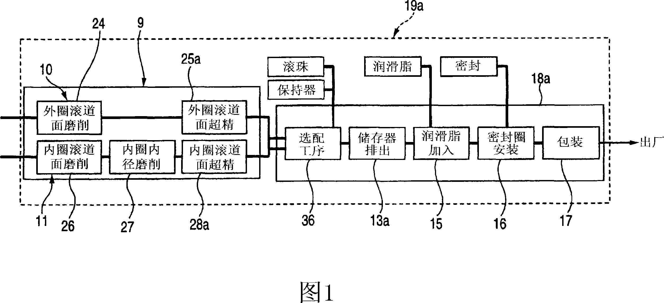
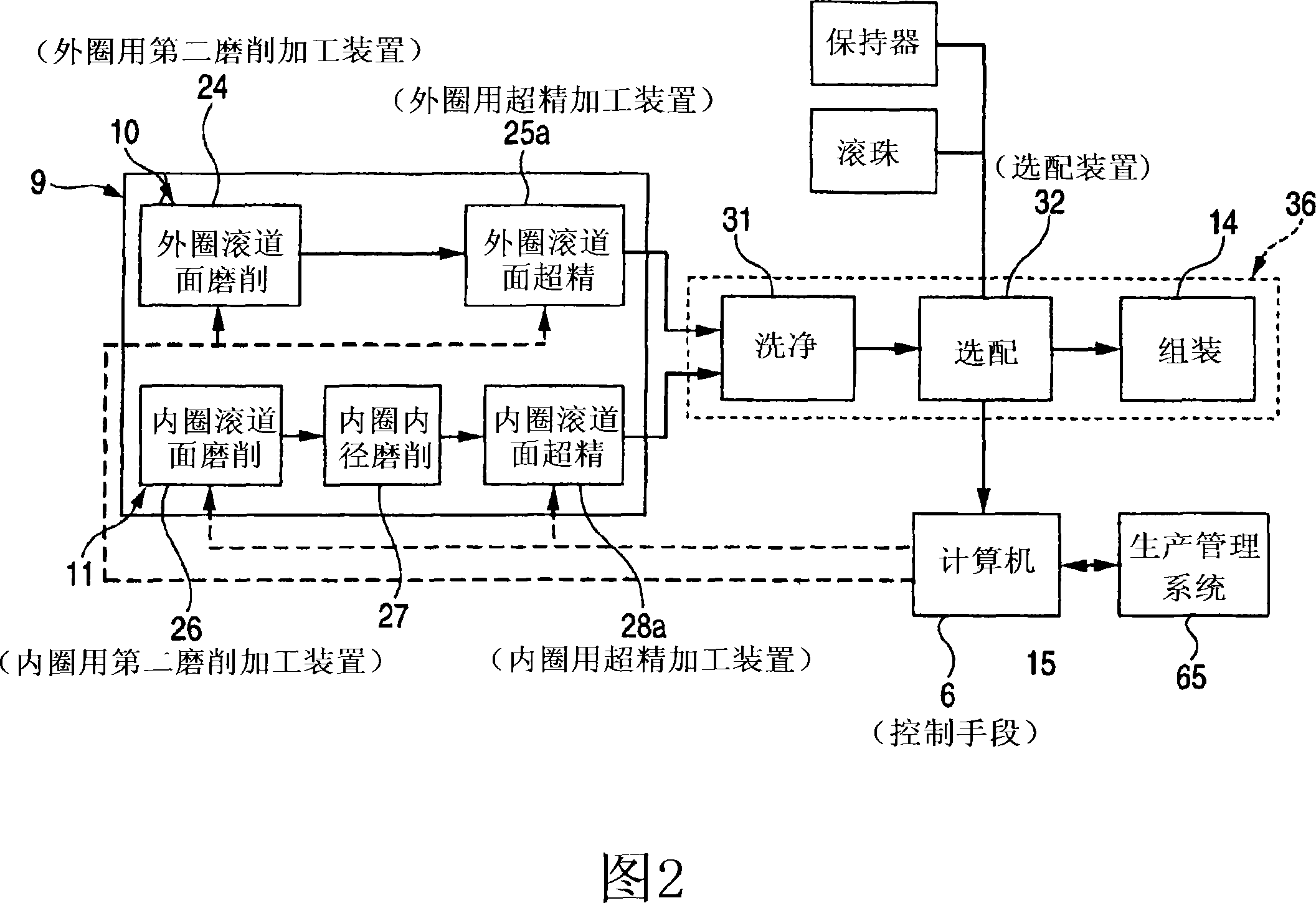
[0131] 1 to 4 show embodiments of the present invention. In the case of the ball bearing manufacturing equipment of this embodiment, the outer ring 1 and the inner ring 2 (refer to FIG. 6 ) of the workpiece (workpiece) or the conveyance direction (flow direction) of the intermediate assembly (left and right in FIG. 1 Direction), between the optional assembly equipment 36 and the grease adding device 15, a reservoir 13a that can accommodate and discharge a plurality of the above-mentioned intermediate assemblies is provided. In addition, as shown in FIG. 2, the optional assembly facility 36 includes a cleaning device 31 for cleaning the outer ring 1 and the inner ring 2 after grinding and superfinishing. An optional device 32 for assembling the outer ring 1, inner ring 2, and balls 3 (refer to Figure 6) of appropriate size, the outer ring 1, inner ring 2, multiple balls 3 and cage delivered from the optional device 32 An assembly device 14 for assembling to form an intermediat...


PUM


Abstract

The invention has a structure: a control device 6 composed of a computer is connected with a detection part of a matching device 32, thus sending detection signals that represent measured values of the diameter of the raceway of an outer ring and the raceway of an inner ring; the control device 6 is further connected with a second grinding process device 24 in the outer ring, a superfinishing device 25a in the outer ring, a second grinding process device 26 in the inner ring and a superfinishing device 28a in the inner ring, so as to be convenient for receiving control signals; according to the measured values of the diameter of the raceway of the outer ring and the raceway of the inner ring that are measured by the detection part, the control device 6 provides change values to diameter-processing target values which are respectively set for the grinding process device 24 (or 26) and the superfinishing device 25a (or 28a) that are used for processing roll surfaces of at least one roll wheel in the outer ring and the inner ring.

Description

technical field [0001] The present invention relates to an improvement of a ball bearing manufacturing facility having a raceway wheel processing facility for processing a ball bearing raceway wheel, an assembly facility for assembling the raceway wheel and balls, and a superfinishing facility used in the manufacturing facility improvement. technical background [0002] As a ball bearing, the structure shown in FIG. 6 is well known. Also, as will be described later, this FIG. 6 shows the clearance of the ball bearing enlarged. This ball bearing is composed of an outer ring 1 and an inner ring 2 arranged concentrically with each other, and a plurality of balls 3, 3 provided therebetween. Among them, the inner circular surface of the outer ring 1 and the outer circular surface of the inner ring 2 respectively form a circle to form the outer ring raceway 4 and the inner ring raceway 5 . The above-mentioned respective balls 3, 3 are arranged between the above-mentioned outer ...

Claims


Application Information

Patent Timeline
Patent Type & Authority Applications(China)
IPC IPC(8): B24B35/00B24B19/06B24B49/03F16C19/06
CPCY10T29/51F16C33/64B24B19/06B24B49/00B24B35/00F16C19/06B24B49/06
Inventor 泉水夏树上西修史入江洋介
Owner NSK LTD
Learn More