Hydraulic tensioner

A tensioning device, hydraulic technology, applied in the direction of transmission, belt/chain/gear, mechanical equipment, etc., can solve problems such as high cost and achieve the effect of reducing manufacturing cost

Inactive Publication Date: 2007-10-24
SCHAEFFLER TECH AG & CO KG
View PDF0 Cites 18 Cited by
  • Summary
  • Abstract
  • Description
  • Claims
  • Application Information

AI Technical Summary

Problems solved by technology

Furthermore, due to the processing direction of the ou

Method used


Image

  • Hydraulic tensioner

Examples


Embodiment Construction

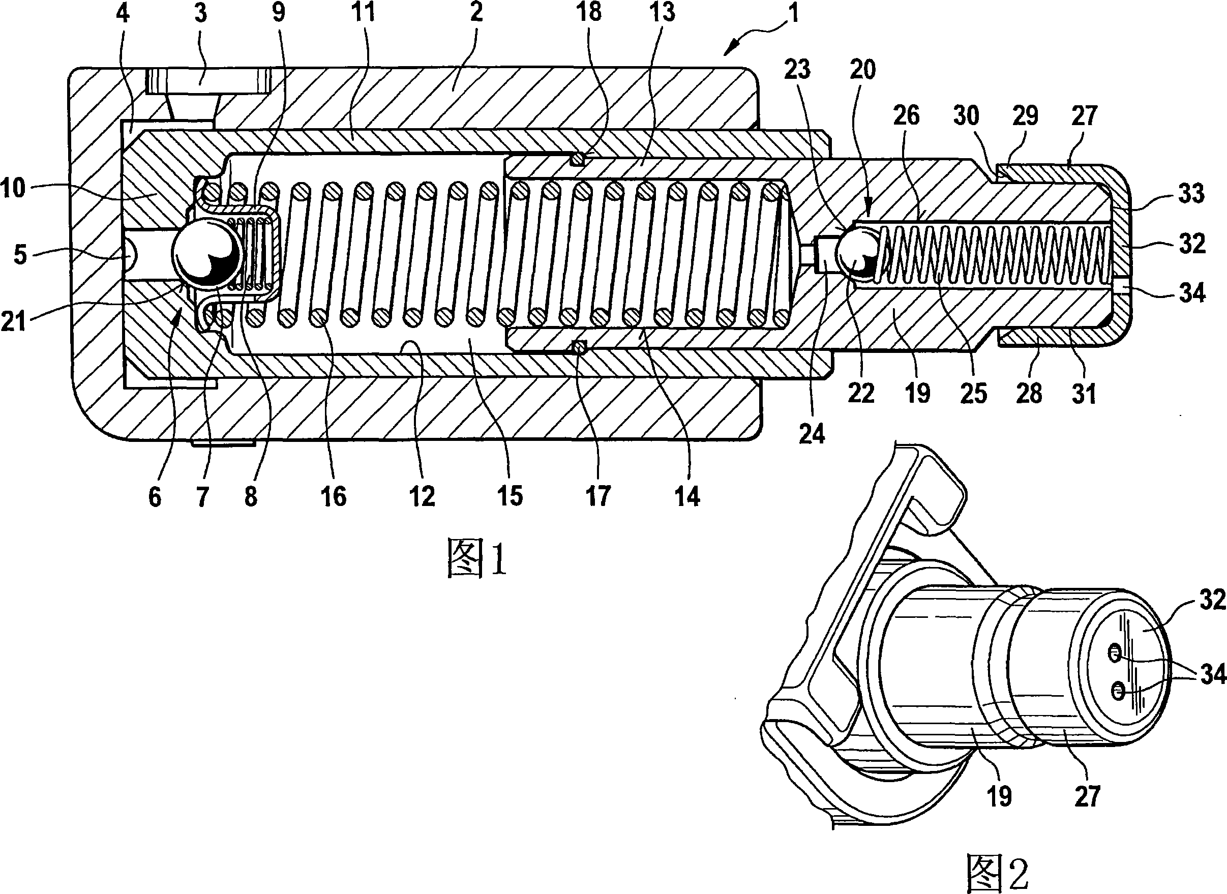
[0026] FIG. 1 shows a longitudinal section through a hydraulic tensioning device 1 with a protective housing 2 . The protective casing 2 is connected to the engine casing, not shown. It has a pressure oil port 3, and lubricating oil from the pressure oil port 3 reaches the valve 6 through the annular space 4 and the transverse groove 5. The valve 6 is located at the bottom 10 of a box 11 which is arranged in the protective case 2 with a sealing clearance. The valve 6 includes a valve ball 7 , a valve seat 21 , a valve spring 8 and a valve sleeve 9 .

[0027] The housing 11 has a blind bore 12 into which a tensioning piston 13 is introduced with sealing play. The tensioning piston 13 contains a blind bore 14 . The blind holes 12 , 14 surround a high-pressure chamber 15 in which a compression spring 16 is arranged. The compression spring 16 acts via the tensioning piston 13 on a not shown tensioning and pulling mechanism. The stroke of the tensioning piston 13 is limited by...


PUM


Abstract

To provide a remote control system which is operable by using a portable terminal only when a person is present near a vehicle.The remote control system is formed of a receiving means for receiving a door locking request signal or a door unlocking request signal, a door locking mechanism, a signal determining means for determining whether a signal received by the receiving means is the door locking request signal or the door unlocking request signal, a locking instructing means for transmitting a locking instruction signal to the locking mechanism, an unlocking instructing means for transmitting an unlocking instruction signal to the locking mechanism, and a person checking means for checking whether or not a person is present near the vehicle, and transmitting a person confirmation signal to the unlocking instructing means. If the signal determining means determines that the signal received by the receiving means is the door locking request signal, the locking instructing means transmits the locking instruction signal to the locking mechanism. If the signal determining means determines that the signal received by the receiving means is the door unlocking request signal, the unlocking instructing means transmits the unlocking instruction signal to the locking mechanism on condition that the locking mechanism receives the person confirmation signal in a predetermined time period.

Description

technical field [0001] The invention relates to a hydraulic tensioning device for a traction mechanism of an internal combustion engine, in particular a hydraulic tensioning device according to the preamble of claim 1 . Background technique [0002] Traction mechanisms such as chain drives or belt drives require optimized initial stress for maximum efficiency and lifetime. Since the length of the traction mechanism changes due to heating and wear, its prestress must be continuously readjusted. Suitable for this purpose is undoubtedly the hydraulic tensioning device. [0003] Such a hydraulic tensioning device has a tensioning piston which can be inserted, for example, into a blind bore of the housing and closes the pressure chamber. A compression spring is located in the pressure chamber, via which the tensioning piston is brought into pressure contact with an element that can guide the traction mechanism. When the tensioning piston is adjusted, additional oil can be intr...

Claims


Application Information

Patent Timeline
IPC IPC(8): F16H7/08
CPCF16H2007/0859F16H2007/0814F16H7/0836F16H2007/0812F16H2007/0806F16H7/08F16H7/12
Inventor 伯特·克鲁恩莱因哈德·科吉
Owner SCHAEFFLER TECH AG & CO KG
Why Eureka
Try Eureka