

Double carrying rope freight traffic cable railway with height-adjustable pylon bent
A freight ropeway and carrying rope technology, which is applied in the field of double carrying rope freight ropeways, can solve the problems of high safety hazard, inability to use, and cannot be adjusted in height, and achieves the effects of high safety and reliability, wide application range and convenient use.
- Summary
- Abstract
- Description
- Claims
- Application Information
AI Technical Summary
Problems solved by technology
Method used
Image

Examples
Embodiment Construction
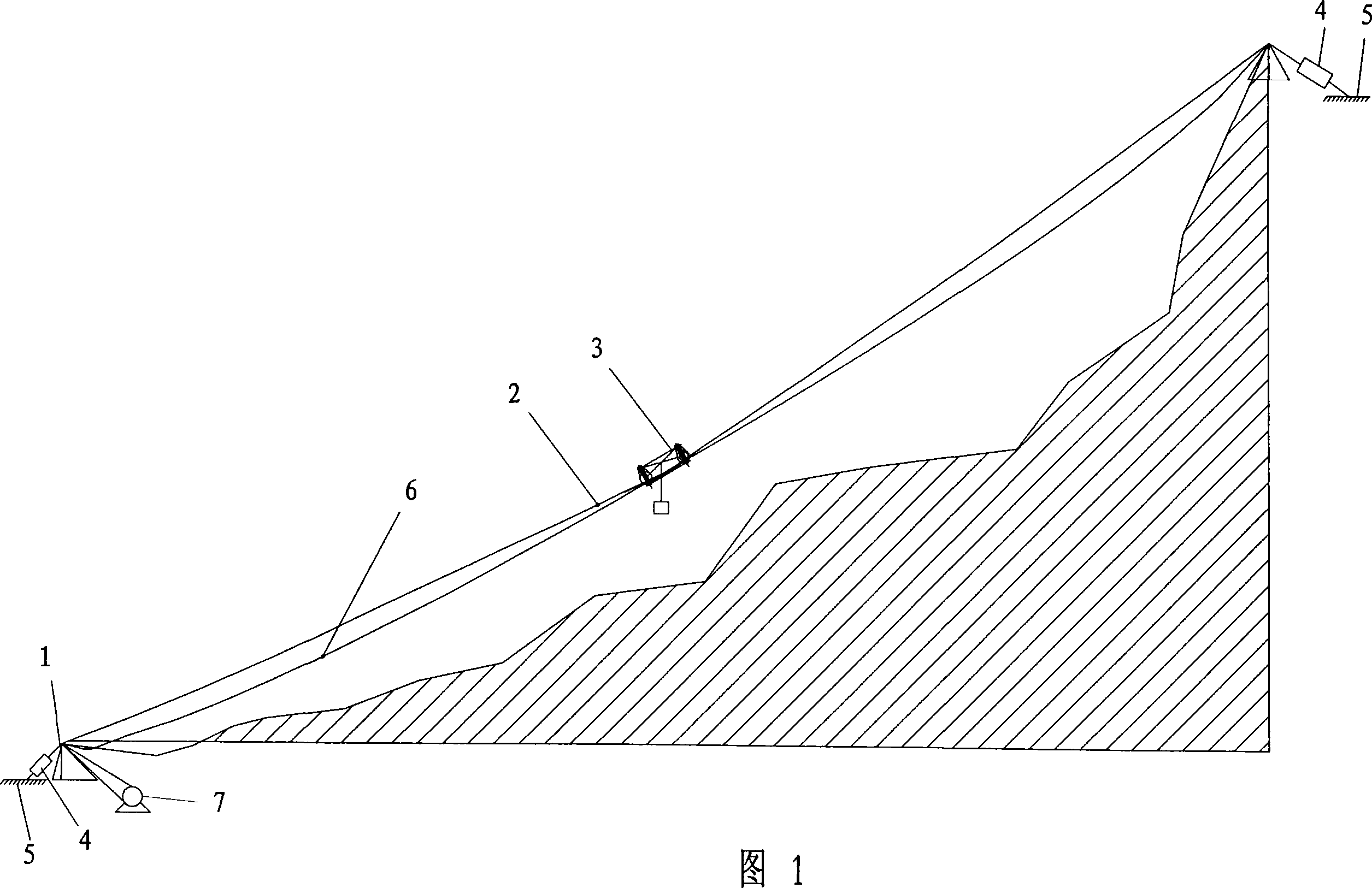
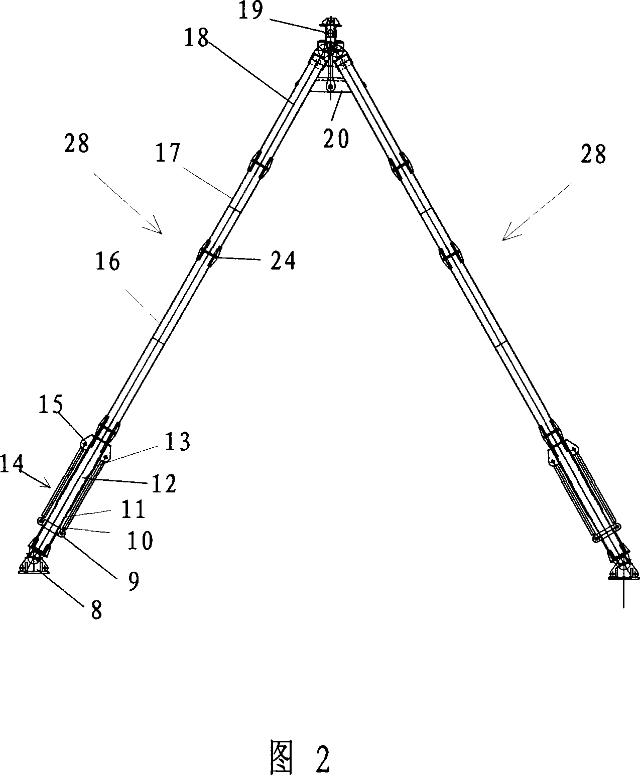
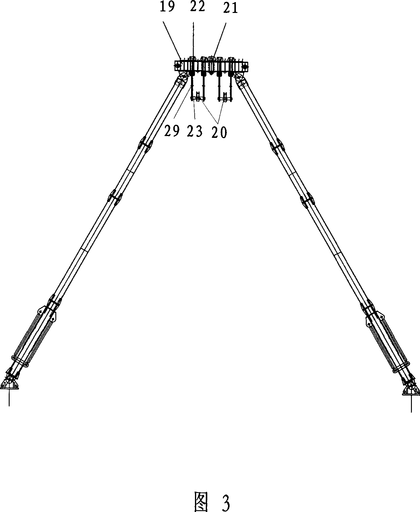
[0016] Referring to Fig. 1 : a double load-bearing cable freight cableway with adjustable tower height, which includes a tower 1, a load-bearing cable 2, a freight trolley 3, a load-bearing cable tensioning device 4, a ground anchor 5, and a circulating traction cable 6. The driving machine 7, the load-carrying cable 2 supporting the cargo trolley 3 is two steel wire ropes, and the four wheels of the cargo trolley 3 supported by a closed frame are supported on the double load-bearing cables 2. This support method can correct the The deviation of the center of gravity causes the wheel to break away from the bearing cable; each leg 28 of the tower 1 is equipped with a length adjustment device, and the length of the leg 28 can be adjusted according to the height of the cableway and the flatness of the terrain; the circulating traction cable 6 and the drive Machine 7 is connected, will not be limited by power supply as driving machine 7 with the motor winch that does not need power...
PUM
 Abstract
Description
Claims
Application Information