Nondestructive detecting method of spring steel decarburized layer deepness
A non-destructive testing and decarburization layer technology, applied in the direction of measuring devices, testing metals, material inspection products, etc., can solve the problems of destructive testing, large errors, and inability to achieve 100% testing, and achieve the effect of simple testing methods
- Summary
- Abstract
- Description
- Claims
- Application Information
AI Technical Summary
Problems solved by technology
Method used
Image

Examples
Embodiment 1
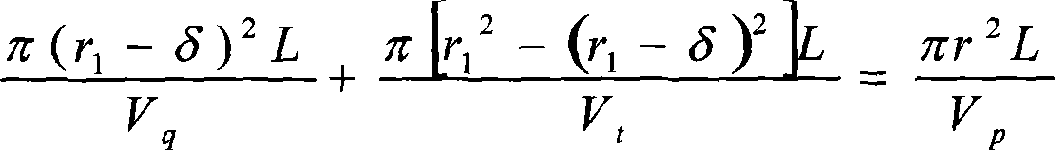
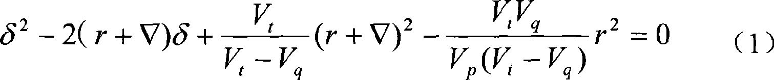
[0023] (1) For the same batch of spring steel with a material of 60Si2Mn and a diameter of φ20, 10 samples were prepared, each with a length of 100mm. Carry out quenching (the work piece is hardened during quenching)-tempering treatment, so that the depth of the decarburized layer of these 10 pieces is 0.1mm, and measure and record the diameter difference of each sample before and after quenching-tempering. Cut and inspect each sample, measure the depth of the decarburized layer under a metallographic microscope, select samples with the depth of the decarburized layer in the range of 0.1±0.01mm, and calculate the average of the difference between the diameters of these samples before and after quenching and tempering Value and record.
[0024] (2) Take 10 samples each three times in sequence to make the depth of the decarburized layer of these samples reach 0.2mm, 0.3mm, 0.4mm respectively. Repeat the above test to obtain the relationship between the depth of the decarburized laye...
Embodiment 2
[0027] (1) For the same batch of spring steel with a material of 60Si2Mn and a diameter of φ30, 10 samples were prepared, each with a length of 100mm. Carry out quenching (the workpiece is hardened during quenching)-tempering treatment to make the depth of the decarburized layer of these 10 pieces at 0.1mm, and measure the diameter difference of each sample before and after quenching-tempering and record it. Cut and inspect each sample, measure the depth of the decarburization layer under a metallographic microscope, select the samples with the depth of the decarburization layer within 0.1±0.01mm, and calculate the average of the difference between the diameters of these samples before and after quenching and tempering Value and record.
[0028] (2) Take 10 samples each three times in sequence to make the depth of the decarburized layer of these samples reach 0.2mm, 0.3mm, 0.4mm respectively. Repeat the above test to obtain the relationship between the depth of the decarburized la...
Embodiment 3
[0031] (1) For the same batch of spring steel with a material of 60Si2Mn and a diameter of φ40, 10 specimens were prepared, each with a length of 100mm. Carry out quenching (the work piece is hardened during quenching)-tempering treatment, so that the depth of the decarburized layer of these 10 pieces is 0.1mm, and measure and record the diameter difference of each sample before and after quenching-tempering. Cut and inspect each sample, measure the depth of the decarburization layer under a metallographic microscope, select the samples with the depth of the decarburization layer within 0.1±0.01mm, and calculate the average of the difference between the diameters of these samples before and after quenching and tempering Value and record.
[0032] (2) Take 10 samples each three times in sequence to make the depth of the decarburized layer of these samples reach 0.2mm, 0.3mm, 0.4mm respectively. Repeat the above test to obtain the relationship between the depth of the decarburized l...
PUM
 Abstract
Description
Claims
Application Information
PatSnap Eureka turns technology decisions into work you can execute. Powered by our Innovation Knowledge Graph, it runs expert workflows across engineering, life sciences, materials and intellectual property. Get your review-ready output in minutes.


