Colourful optical filter

A color filter, red light technology, applied in the field of color filters, can solve the problems of reducing the color saturation of liquid crystal displays, unsatisfactory red, green and blue spectral resolution, and low material utilization rate, etc., to improve the color The effect of saturation

Inactive Publication Date: 2007-10-31
WINTEK CORP
View PDF0 Cites 24 Cited by
  • Summary
  • Abstract
  • Description
  • Claims
  • Application Information

AI Technical Summary

Problems solved by technology

First of all, as far as the manufacturing process is concerned, since the red, green, and blue pigments and photoresist are formed on the glass substrate by spin coating, the material utilization rate of this method is quite low, so a considerable amount of waste will be wasted. More materials make the cost relatively higher
Furthermore, as far as the manufactured optical filter is concerned, the resolution of the filtered red, green and blue light spectra of the color filter formed by the pigment dispersion method is not ideal, which will reduce the brightness of the liquid crystal display when it is displayed. color saturation

Method used


Image

  • Colourful optical filter
  • Colourful optical filter
  • Colourful optical filter

Examples


Embodiment Construction

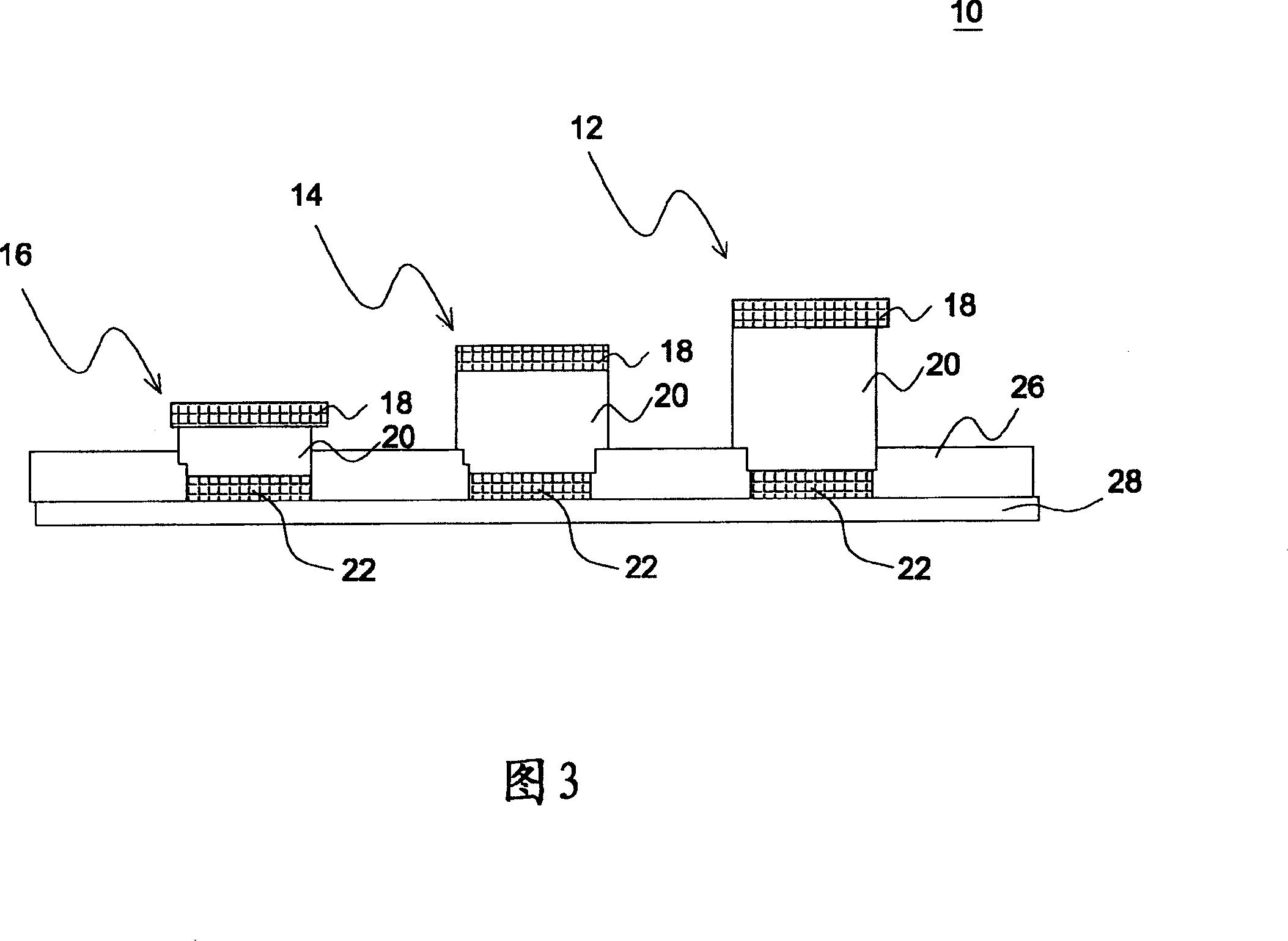
[0040] FIG. 3 is a cross-sectional structure diagram showing a color filter 10 according to an embodiment of the present invention. The color filter 10 has a red light (R) penetrating area 12, a green light (G) penetrating area 14 and a blue light (B) penetrating area 16 formed by a pixel unit corresponding to the liquid crystal display, and two adjacent penetrating areas The intervals are separated by the black matrix layer 26 formed on the transparent substrate 28 to prevent adjacent color lights from mixing with each other.

[0041] As shown in FIG. 3 , each penetrating region of the color filter 10 is composed of a three-layer film structure formed on a transparent substrate 28, including a first reflective layer 18, a gap layer 20 and a second reflective layer. 22, and the gap layer 20 is interposed between the first reflective layer 18 and the second reflective layer 22 arranged in parallel. The reflective layers 18 , 22 and the spacer layer 20 can be formed on the mult...


PUM

PropertyMeasurementUnit
thicknessaaaaaaaaaa
thicknessaaaaaaaaaa
thicknessaaaaaaaaaa

Abstract

This invention discloses one color filter slice, which comprises one transparent baseboard, one top reflection layer, one bottom reflection layer, one gap adjusting gap layer and one interference layer, wherein the gap layer is set between top reflection layer and bottom reflection layer with three different thickness values on one pixel unit to form color filter slice of red, green and blue one; the interference layer forms top reflection layer relative to red position.

Description

technical field [0001] The invention relates to a color filter, in particular to a color filter structure using the principle of thin film interference. Background technique [0002] The color filter is a key component that determines the color, contrast, luster, sharpness and saturation of a color LCD panel, and it accounts for a relatively high proportion of the cost of the LCD panel. FIG. 1 is a schematic diagram of a color filter 100 of a liquid crystal display. As shown in Figure 1, different filter layers 104, 106, 108 of the three primary colors of red (R), green (G) and blue (B) are formed on the glass substrate 102, and chrome-like layers are formed between two adjacent filter layers. A metal black matrix layer (BM) 110 is used to prevent adjacent colors from mixing, and finally a transparent electrode 112 is formed on the top. [0003] At present, the main commercialized color filter manufacturing method is the pigment dispersion method, and the process of the pi...

Claims


Application Information

Patent Timeline
Patent Type & Authority Applications(China)
IPC IPC(8): G02B5/23G02F1/1335
Inventor 陈健忠黄敬佩
Owner WINTEK CORP
Why Eureka
Try Eureka