
Microwave transmission system

A microwave transmission and microwave technology, applied in the direction of waveguide, waveguide-type devices, circuits, etc., can solve problems that are susceptible to interference and cannot be applied to high-reliability fields, and achieve the effect of high-speed data transmission

Inactive Publication Date: 2007-10-31
SHANGHAI ZHENHUA HEAVY IND
View PDF0 Cites 6 Cited by
  • Summary
  • Abstract
  • Description
  • Claims
  • Application Information

AI Technical Summary

Problems solved by technology

However, this communication method is susceptible to interference and cannot be used in some fields that require high reliability, such as automatic control of dock container cranes, etc.

Method used


Image

  • Microwave transmission system
  • Microwave transmission system
  • Microwave transmission system

Examples


Embodiment Construction

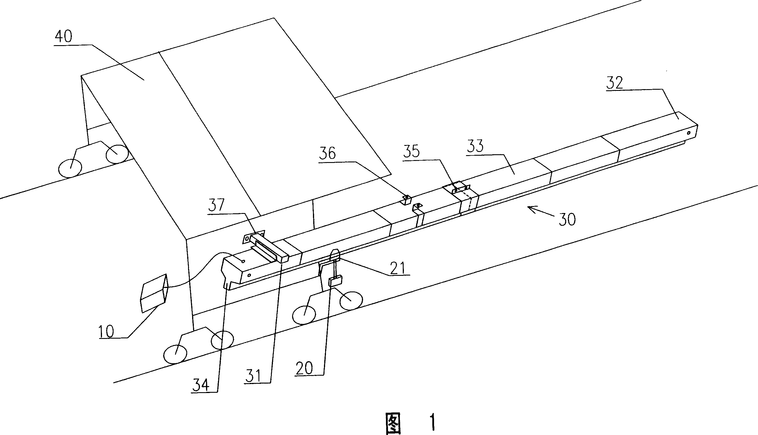
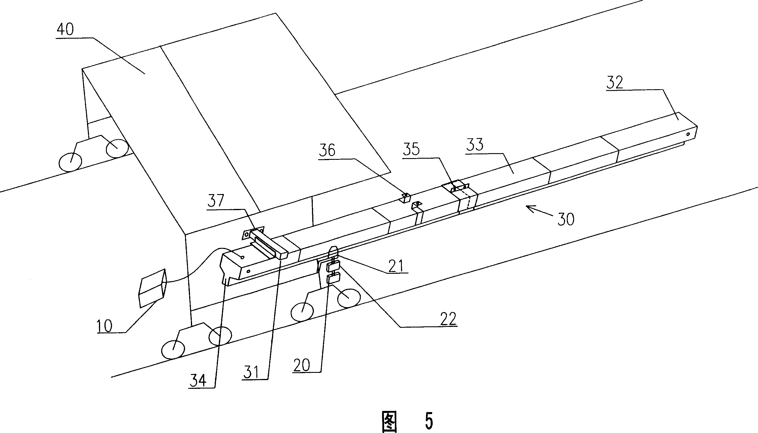
[0020] Referring to FIG. 1 , an embodiment of the microwave transmission system of the present invention mainly includes a transmitter 10 , a receiver 20 , and a microwave transmission pipe 30 . The transmitter 10 is fixedly set to transmit data from the monitoring center. The transmission frequency and data transmission rate of the transmitter 10 can be adjusted, and the transmission rate can reach 10Mbit / s. The receiver 20 is arranged on the track machinery equipment 40 and runs along with the track machinery equipment 40 ; the receiver 20 is connected with a sheet antenna 21 .

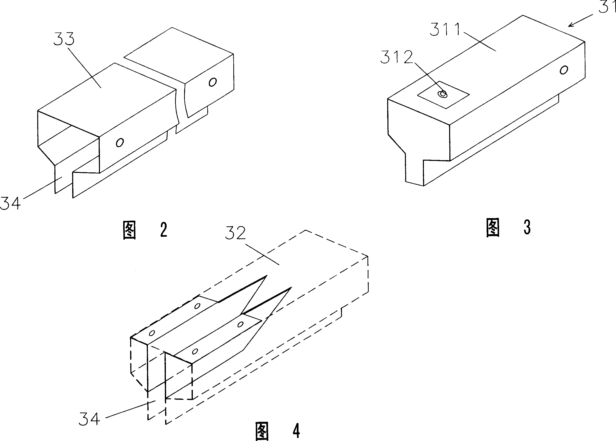
[0021] The microwave transmission pipe 30 is arranged along the running track of the track machinery equipment 40, and its head end is connected to the transmitter 10 through a cable, and its end is closed, serving as a pipe for microwave signal transmission. The bottom of the microwave transmission pipe 30 is provided with a downward opening conduit groove 34 from the head end to the end, and the c...


PUM


Abstract

The invention discloses a microwave transmission system that comprises a fixed emitter (10) and a receiver (20) which is set on a track mechanical equipment (40), said receiver is connected with a antenna (21), it characterized in that it also includes a microwave transmission pipe (30) which is set along the running track of the track mechanical equipment, head of said microwave transmission pipe is connected with said emitter, the end is closed; a canal groove (34) whose opening is downwards is set at bottom of said microwave transmission pipe from head to end, the antenna of said receiver is inserted into the inner of the microwave transmission pipe from said canal groove, and runs along said canal groove, it transfers the microwave signal to the receiver. The microwave transmission system in the invention can provide non-contact, reliable, high speed data to the track mechanical equipment.

Description

technical field [0001] The invention relates to a microwave transmission system, in particular to a data transmission system using a microwave transmission pipeline to transmit microwaves. Background technique [0002] In the field of automation applications, the communication between track mechanical equipment (that is, mechanical equipment walking along a fixed track) and the monitoring center usually uses optical cables, that is, the track mechanical equipment is connected to the monitoring center through an optical cable, and the optical cable is retracted by a reel when walking. . Although this communication method can meet the communication requirements, it has the disadvantages of limiting the running speed and running distance of track mechanical equipment and large installation space. [0003] In order to overcome the shortcomings of this communication method, wireless communication methods can be used, such as open microwave transmission. A transmitter is installe...

Claims


Application Information

Patent Timeline
Patent Type & Authority Applications(China)
IPC IPC(8): H01P3/00
Inventor 王建飞
Owner SHANGHAI ZHENHUA HEAVY IND
Learn More