Member for cast-in-place concrete

A technology for reinforced concrete and components, which is applied to building components, on-site preparation of building components, building construction, etc., can solve the problems of troublesome hollow tube production, high cost, and increased hollow floor cost.

Inactive Publication Date: 2007-11-07
邱则有
View PDF0 Cites 0 Cited by
  • Summary
  • Abstract
  • Description
  • Claims
  • Application Information

AI Technical Summary

Problems solved by technology

In this way, the production of the hollow tube is troublesome and the cost i

Method used


Image

  • Member for cast-in-place concrete
  • Member for cast-in-place concrete
  • Member for cast-in-place concrete

Examples


Embodiment Construction

[0049] The present invention will be further described below in conjunction with the accompanying drawings and embodiments.

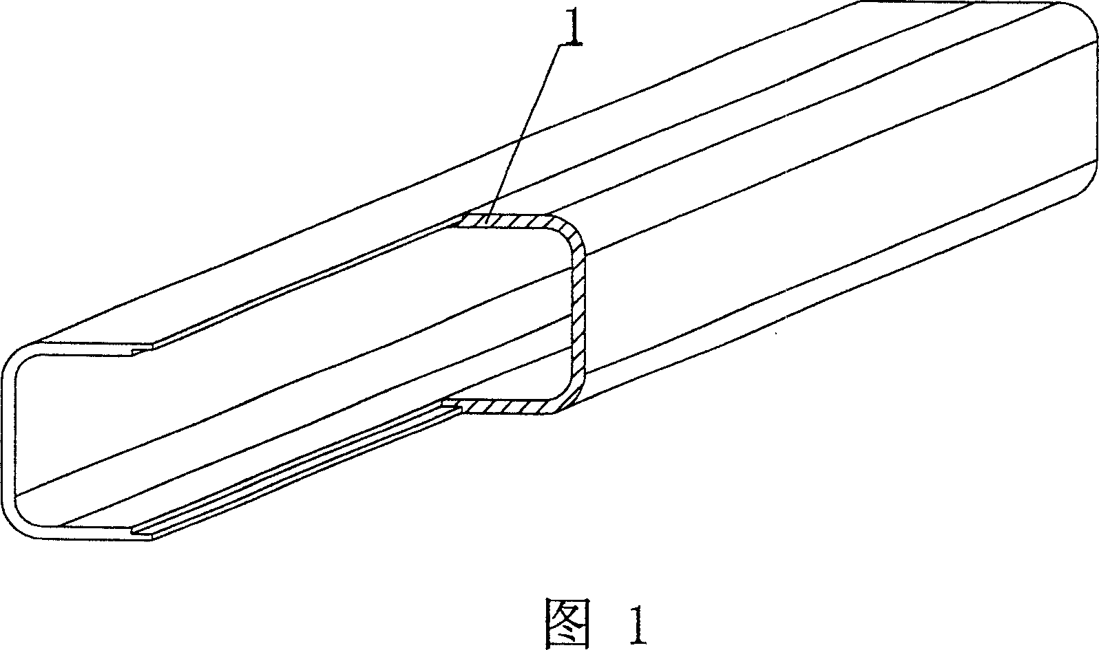
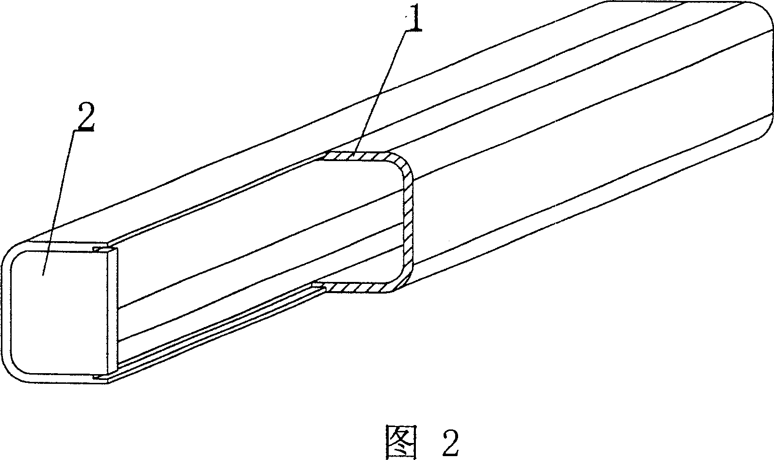
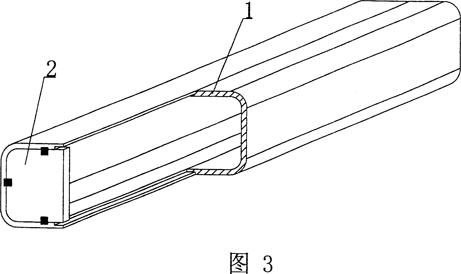
[0050] As shown in the accompanying drawings, the present invention is characterized in that the components are fastened and fixed by two half parts 1. The two half parts 1 are basin-shaped parts. Out of or recessed into the pot edge of the pot-shaped half part 1. In the accompanying drawings, 1 is a half part, and in each accompanying drawing, those with the same numbering have the same description. As shown in FIG. 1 , the component is formed by fastening and fixing two half parts 1 to each other. As shown in Figure 7, Figure 9, Figure 10, and Figure 14, the two half parts 1 are basin-shaped parts, and the fastening position of the half parts 1 has a buckle structure, and the buckle structure is partially higher than the basin mouth of the basin-shaped half part 1 side.

[0051] The invention is also characterized in that at least one end of the ha...


PUM


Abstract

The member for in-situ cast reinforced concrete consists of two basin shaped parts combined and fixed mutually, and the buckling structure in the joint between two parts has local raised or notched section. The present invention is suitable for in-situ cast or pre-stressed reinforced concrete hollow floor slab, roof, wall, foundation slab and hollow bridge, especially hollow flat floor slab.

Description

[0001] This application is a divisional application of an invention patent application with an application date of December 22, 2002, an application number of 02158266.1, and a title of "a component for cast-in-place reinforced concrete". (1) Technical field [0002] The invention relates to a component for cast-in-place reinforced concrete. (2) Background technology [0003] At present, in the prior art, the hole-forming components of the cast-in-place hollow floor slab are permanent mandrels, such as paper tubes, plastic tubes, metal bellows, and lightweight materials for mandrels. These tubular mandrels or components are mainly considered to evacuate the concrete and reduce the weight of the floor slab. For example, the patent No. ZL99249775.8 applied by the applicant is a utility model patent named "fiber-reinforced thin-walled tube for filling cast-in-place reinforced concrete". It consists of a hard thin-walled tube and plugs at both ends. The two ends of the hard thi...

Claims


Application Information

Patent Timeline
IPC IPC(8): E04C1/00E04B5/16E04B5/36E04G15/06
Inventor 邱则有
Owner 邱则有
Why Eureka
Try Eureka