Apparatus for operating gas and providing for observing under vacuum or low-voltage environment

A low-pressure environment, gas technology, applied in the direction of measuring devices, electrical components, instruments, etc., can solve problems such as operation, electron beam cannot be imaged smoothly, and electron beam focusing distance changes

Inactive Publication Date: 2007-11-07
CONTREL TECH CO LTD
View PDF0 Cites 6 Cited by
  • Summary
  • Abstract
  • Description
  • Claims
  • Application Information

AI Technical Summary

Problems solved by technology

[0006] Although the aforementioned technology can form extremely low-pressure water vapor in the water vapor layer, however, there are many deficiencies that need to be improved:
[0007] 1. The original design of the electron microscope must be changed, and the electron microscope must be disassembled. Not only is the process extremely complicated, it must be done by professionals, and its cost is also extremely expensive, and it is easy to damage the electron microscope, which makes this technology Cannot be mass-produced so far
[0008] 2. Increasing the height of the sample chamber of the electron microscope will cause a change in the focusing distance of the electron beam, resulting in a loss of phase difference and resolution
[0009] 3. Increasing the gas pressure in the gas chamber will cause the gas to leak from the outermost perforation 763 in Fig. 22 to the vacuum area, thus making it impossible to operate under normal pressure inside the gas chamber; although the pumping capacity of the buffer chamber 766 is greatly increased This gas leakage problem can be overcome, but the rapid gas extraction rate will cause the gas to generate serious eddy currents near the opening of the internal perforation 763, resulting in multiple scattering of electrons, resulting in the failure of electron beam imaging or electron diffraction experiments
[0013] In addition, Hui et al.'s technique fixes the entire environmental device inside the microscope, so it is very difficult and extremely difficult to install the electron beam through the coaxial perforation of the environmental device.
And the technology of people such as Gai also faces the difficulty of aligning the upper and lower pole pieces 66 at the same time.
In addition, because Hui's environmental design is a fixed design (fixed on the pole below), it is impossible to adjust the height of the entire environmental device, and lose the opportunity to achieve accurate focusing by handing over the focusing area

Method used


Image

  • Apparatus for operating gas and providing for observing under vacuum or low-voltage environment
  • Apparatus for operating gas and providing for observing under vacuum or low-voltage environment
  • Apparatus for operating gas and providing for observing under vacuum or low-voltage environment

Examples


Embodiment Construction

[0097] In order to describe the structure and characteristics of the present invention in detail, the following eleven preferred embodiments are given and described in conjunction with the drawings as follows, wherein:

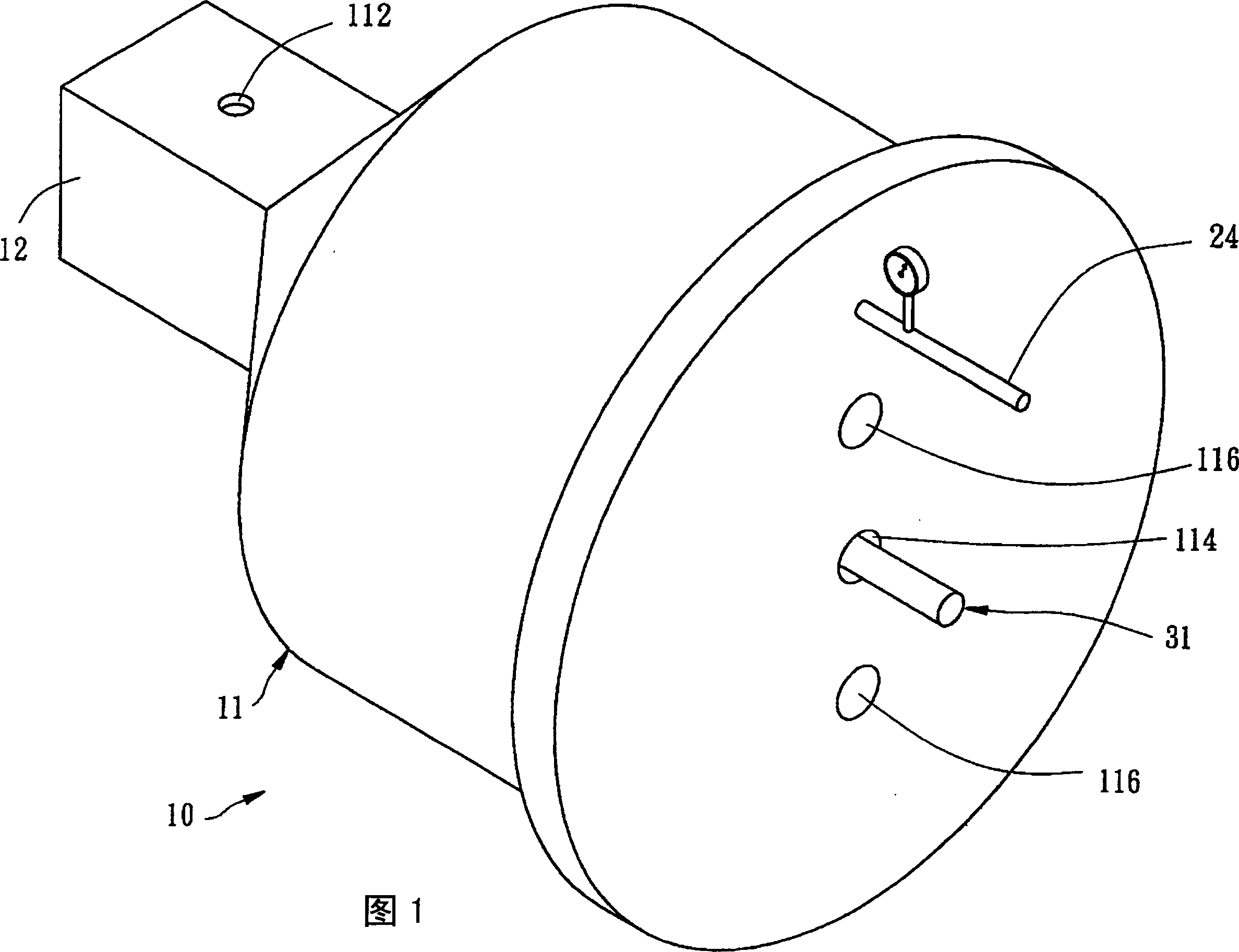
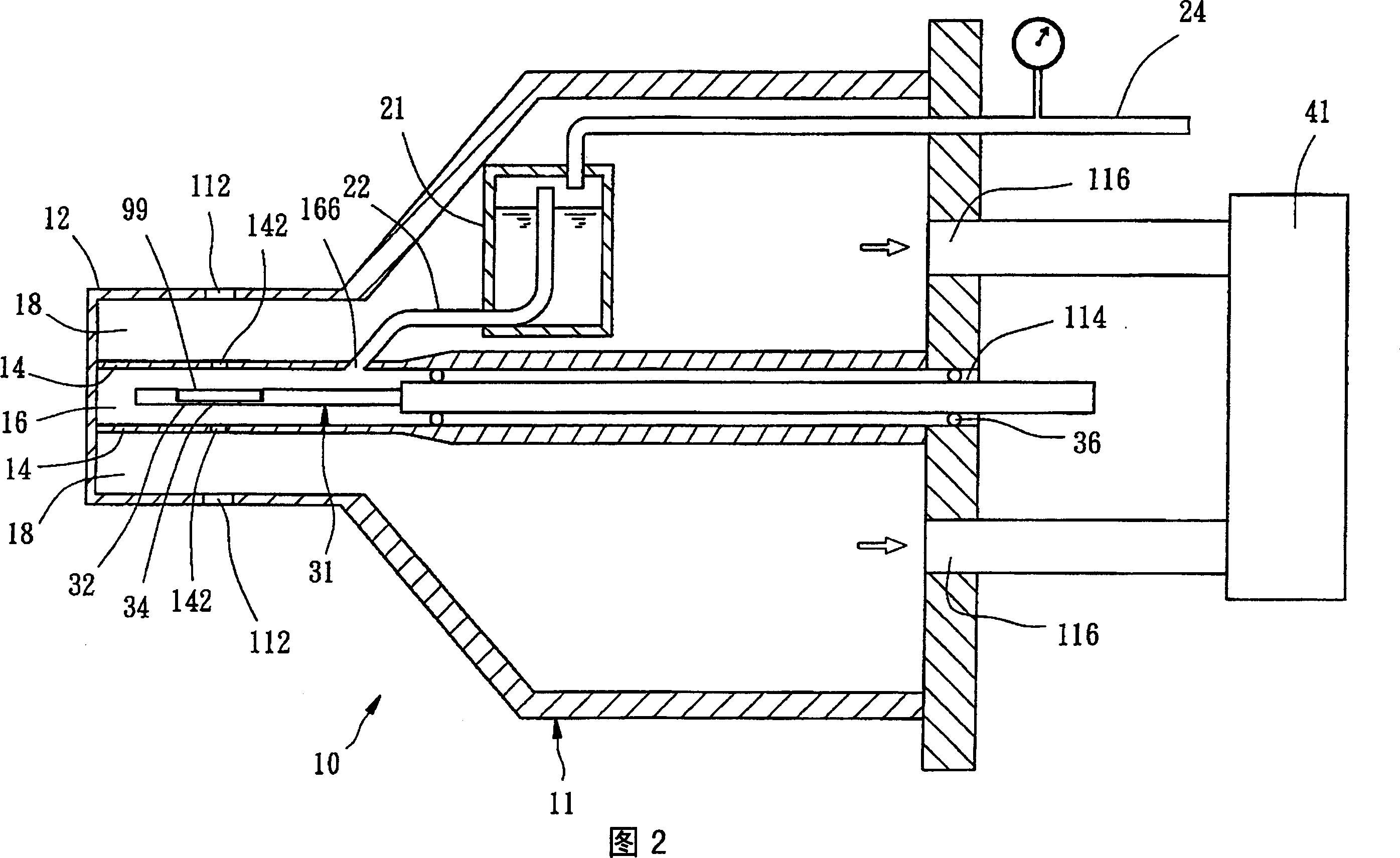
[0098] As shown in Figures 1 to 2, the first preferred embodiment of the present invention provides an observational device 10 for operating gas in a vacuum or low-pressure environment, which mainly includes:

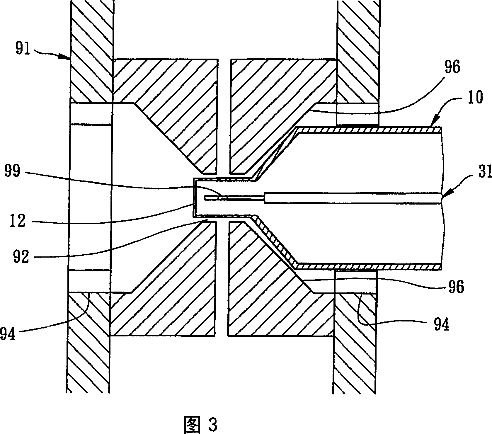
[0099] A housing 11, one side forms a flatter portion 12, the thickness of this flatter portion 12 is approximately less than the distance between the upper and lower diode blocks 96 in the sample chamber 92 (shown in Figure 3) (specimen chamber) of the electron microscope 91, Usually this distance is no more than one centimeter. There are several partitions 14 inside the casing 11, and an air chamber 16 is formed by partitioning the inside of the casing 11, and a buffer chamber 18 is respectively formed on the top and bottom of the outside of the air ch...


PUM


Abstract

This invention relates to a device for operating gas at vacuum or low gas pressure for observation including: a shell with a flat part formed at one side and at least one clapboard in it to divide it into a gas chamber and a buffer chamber, in which, the clapboard of the top underside of the gas chamber is set with an internal hole, an outer hole is set at the top and bottom of the shell separately, the internal hole and the outer hole are coaxial and placed at the flat part, said shell has a pumping hole connected to the buffer chamber and a gas injecting hole connected to the gas chamber.

Description

technical field [0001] The present invention is related to the technique of operating gaseous substances in vacuum or low-pressure environment, and in particular refers to an observable device for operating gas in vacuum or low-pressure environment. Background technique [0002] In terms of observation technology at the microscopic scale, it is currently known that the electron microscope is used to achieve the highest magnification effect. Through the ultra-high magnification of the electron microscope, people can conduct related scientific research on the nanostructure of matter. [0003] The principle of the electron microscope is to use electron beams to detect objects. It must accelerate electrons through high voltage in a vacuum environment and use electromagnetic lens focusing to achieve nanostructure observation. As shown in Figure 20, the electron microscope 61 has A sample chamber 62 (specimen chamber) can be used for sample insertion, and the interior of the sampl...

Claims


Application Information

Patent Timeline
Patent Type & Authority Applications(China)
IPC IPC(8): H01J37/20H01J37/02G01N1/00G01N27/00G01N13/00
Inventor 赵治宇谢文俊
Owner CONTREL TECH CO LTD
Why Eureka
Try Eureka