Method for laser in-situ repairing cavitation-vane gas turbine

An in-situ repair, steam turbine technology, applied in the direction of laser welding equipment, welding media, welding/welding/cutting items, etc.

Inactive Publication Date: 2007-11-21
BEIJING UNIV OF TECH
View PDF0 Cites 9 Cited by
  • Summary
  • Abstract
  • Description
  • Claims
  • Application Information

AI Technical Summary

Problems solved by technology

[0005] The purpose of the present invention is to overcome the difficult problem that large lasers such as CO2 cannot go to the site to realize the in-situ repair of blades, and provide a laser in-situ repair method for steam turbine cavit

Method used


Image

  • Method for laser in-situ repairing cavitation-vane gas turbine
  • Method for laser in-situ repairing cavitation-vane gas turbine
  • Method for laser in-situ repairing cavitation-vane gas turbine

Examples


Embodiment Construction

[0017] This embodiment will be described in detail below in conjunction with the accompanying drawings.

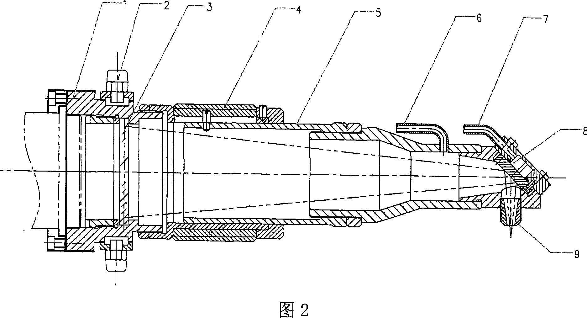
[0018] Because the distance between the blades of the steam turbine and the distance between the last stage of the steam turbine and the second last stage is very small, ordinary laser working heads cannot achieve cladding. Therefore, optical path turning and secondary focusing technologies are adopted in the laser working head to achieve The laser working head can reach the repair position, as shown in Figure 2. The laser working head is connected to the coupling output device of the laser through the connection seat 1, and the transmission mirror 3 made of ZnSe material is cooled through the cooling water circuit 2. The transmission mirror 3 realizes the initial convergence of the laser beam, and the length of the laser head is adjustable. Relying on the outer sleeve 4 and the inner sleeve 5 to achieve expansion and contraction, the protective gas 6 prevents impurities f...


PUM


Abstract

The invention is concerned with laser in situ remediation method for steam turbine cavitation vane, belonging to laser machining technology field. The laser bean sent from laser transfers to laser work head, and in the laser work head, laser bean converges to the reflecting mirror through transmission mirror. The axis line to beam of light converged by reflecting mirror and transmission mirror is 30 to 60 degree, and the laser bean reflected by reflecting mirror to the steam turbine cavitation surface through muzzle. There is feeding equipment to powder on the place of muzzle, and the anti- cavitation stuff fed by feeding equipment to powder is melted by laser and repairs the cavitation surface. The beam of light sent by laser repairs the cavitation surface and the laser bean turns in the laser work head to reach the position to be repaired of vane, and this realizes the in situ remediation of the steam turbine vane at narrow space without disassembly.

Description

technical field [0001] The invention relates to a laser in-situ repair method for steam turbine cavitation blades, and belongs to the technical field of laser processing. Background technique [0002] The steam turbine blade is an extremely important component in the electric power industry. It is used to convert the linear motion of the high-temperature and high-pressure gas into the rotation of the steam turbine shaft. The steam turbine operates at a speed of 3000 rpm. There are mainly two types of failure modes of steam turbine blades. One is blade fracture, which mainly occurs at the root of the blade, and this failure form is irreparable. Another failure mode is cavitation, which mainly occurs on the top surface of the blade, and the cavitation damaged blade can be repaired and reused. The cause of cavitation is that the steam turbine blades have been impacted by water vapor for a long time, and the edges of the blades are eroded, forming a large number of cavitation ...

Claims


Application Information

Patent Timeline
IPC IPC(8): B23K26/34B23K26/06B23K35/24C23C24/10B23K101/00
Inventor 杨胶溪李强于振声闫婷
Owner BEIJING UNIV OF TECH
Why Eureka
Try Eureka