
Bi-spiral flow smokeless steam boiler with chain grates

A chain grate and steam boiler technology, applied in the direction of combustion method, combustion chamber, solid fuel combustion, etc., can solve the problems of affecting heat conduction effect, reducing the comprehensive utilization rate of energy, reducing the service life of pipes, etc. The effects of black smoke and dust accumulation on the heated area, simple and reasonable structure, and low cost

Inactive Publication Date: 2007-11-21
王树洲
View PDF0 Cites 5 Cited by
  • Summary
  • Abstract
  • Description
  • Claims
  • Application Information

AI Technical Summary

Problems solved by technology

[0003] Although the "pot" of these products is designed with sufficient heating surface, a large amount of dust accumulates in the heat exchange parts of the tangled and vertical tubes, which seriously affects the effect of heat conduction. At the same time, because of the backward combustion technology used, the concentration of smoke and dust is very high. , a large part of these granular dusts are "coking carbon particles" that have not been burned out in the "furnace". a large amount of coal resources
During the operation of the whole boiler equipment, the Ringelmann blackness of the flue gas exhausted in the light load state is ≤1 level. However, the enterprise users generally operate in the full load or overload state, but at this time the boiler is black. Smoke, the combustible component "volatile matter" in bituminous coal is discharged into the atmosphere in the form of smoke, and the tar soot on the heat exchange surface will also accumulate in large quantities, which seriously reduces the thermal efficiency. The carbon content of the discharged ash is above 28-30%. The comprehensive utilization rate of energy is greatly reduced, which wastes energy and pollutes the environment. This is a "worldwide problem" in the boiler industry

Method used


Image

  • Bi-spiral flow smokeless steam boiler with chain grates
  • Bi-spiral flow smokeless steam boiler with chain grates
  • Bi-spiral flow smokeless steam boiler with chain grates

Examples


Embodiment Construction

[0023] The present invention will be further described below in conjunction with the accompanying drawings of the embodiments.

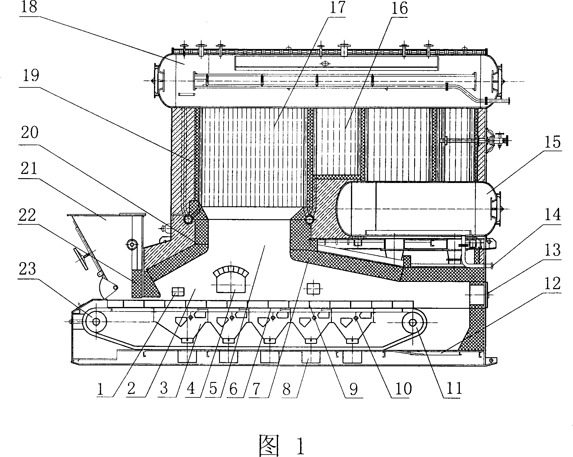
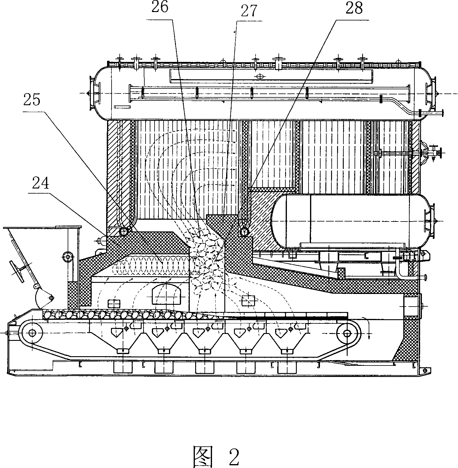
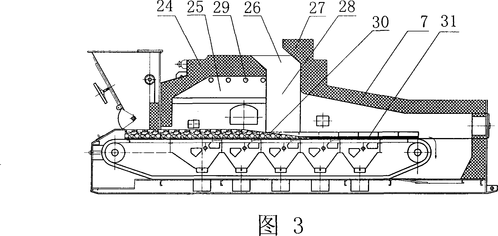
[0024] As shown in Fig. 2, Fig. 3 and Fig. 4, the chain grate type double swirl pure smokeless steam boiler according to the present invention, on the basis of the existing SZL type chain grate type steam boiler shown in Fig. 1, except Except for the coal-burning device, other structures still use the original structure, including the shell, the water wall 17, the convection tube group 16, the upper and lower drums 18, 15 and the lower coal-burning device. The coal-burning device is composed of a coal hopper 21 and a coal gate 22. The coal loading device, the chain grate 6, the front arch and the rear arch 7, the back furnace is formed between the rear arch 7 and the chain grate 6, the front furnace 2 is formed between the front arch and the chain grate 6, the front furnace 2. Upper hearth 25 and lower hearth 42. The upper and lower hearths 25 and 42...


PUM


Abstract

The invention relates to a chain grate and double swirl smokeless steam boiler, a thermal equipment, including shell, water wall, convection of the group, the drum and lower coal-fired devices, the coal-fired device includes coal installation, chain grate , the front furnace arch and the back furnace arch on the coal-fired, between the front arch and a chain grate constitute the front hearth, between the back furnace arch and the chain grate constitute back hearth, between the front furnace arch and the back furnace arch have the combustion gas export, the front hearth fall into upper hearth and nether hearth ,and its cross-section present two symmetry R form structure, the nether hearth of the two R form front hearth communicate, on the front hearth side wall has a tuyere open into upper hearth , the back of the front hearth connect the combustion gas export. The structure is simple reasonable, and low cost, full combustion, high thermal efficiency, low energy consumption, solved black smoke fouling problems, protection of the environment.

Description

technical field [0001] The invention relates to a chain grate type double swirl pure smokeless steam boiler, which belongs to thermal equipment. Background technique [0002] At present, the large-scale chain grate steam boiler, which has been vigorously promoted in China and has more advanced performance, belongs to the SZL series products. The structure includes the shell, water-cooled wall, convection tube group, drum and lower coal-fired device. Coal loading device, chain grate, furnace front arch and furnace rear arch. The front furnace is formed between the furnace front arch and chain grate, and the rear furnace is formed between the furnace rear arch and chain grate. There are combustion hot gas outlets between them, and the thermal power is 4.2MW-30MW, or even larger. All major boiler factories have finalized drawings and manufacturing inspection standards issued by the Ministry of Labor. [0003] Although the "pot" of these products is designed with sufficient hea...

Claims


Application Information

Patent Timeline
IPC IPC(8): F23B40/00F23M5/06
Inventor 王树洲
Owner 王树洲
Features
  • Generate Ideas
  • Intellectual Property
  • Life Sciences
  • Materials
  • Tech Scout
  • Unparalleled Data Quality
  • Higher Quality Content
  • 60% Fewer Hallucinations
Learn More