Hot gas flow reversion burner

A technology of combustion device and hot air flow, which is applied to combustion equipment, solid fuel combustion, lighting and heating equipment, etc., can solve the problems of insufficient fuel combustion, waste of energy, pollute the environment, etc., achieve less ash, save fuel, powerful effect

Inactive Publication Date: 2007-11-28
李寄陶
View PDF0 Cites 1 Cited by
  • Summary
  • Abstract
  • Description
  • Claims
  • Application Information

AI Technical Summary

Problems solved by technology

[0003] In order to solve the problems of insufficient fuel combustion, waste of energy and pollution of the environment

Method used


Image

  • Hot gas flow reversion burner
  • Hot gas flow reversion burner
  • Hot gas flow reversion burner

Examples


Example Embodiment

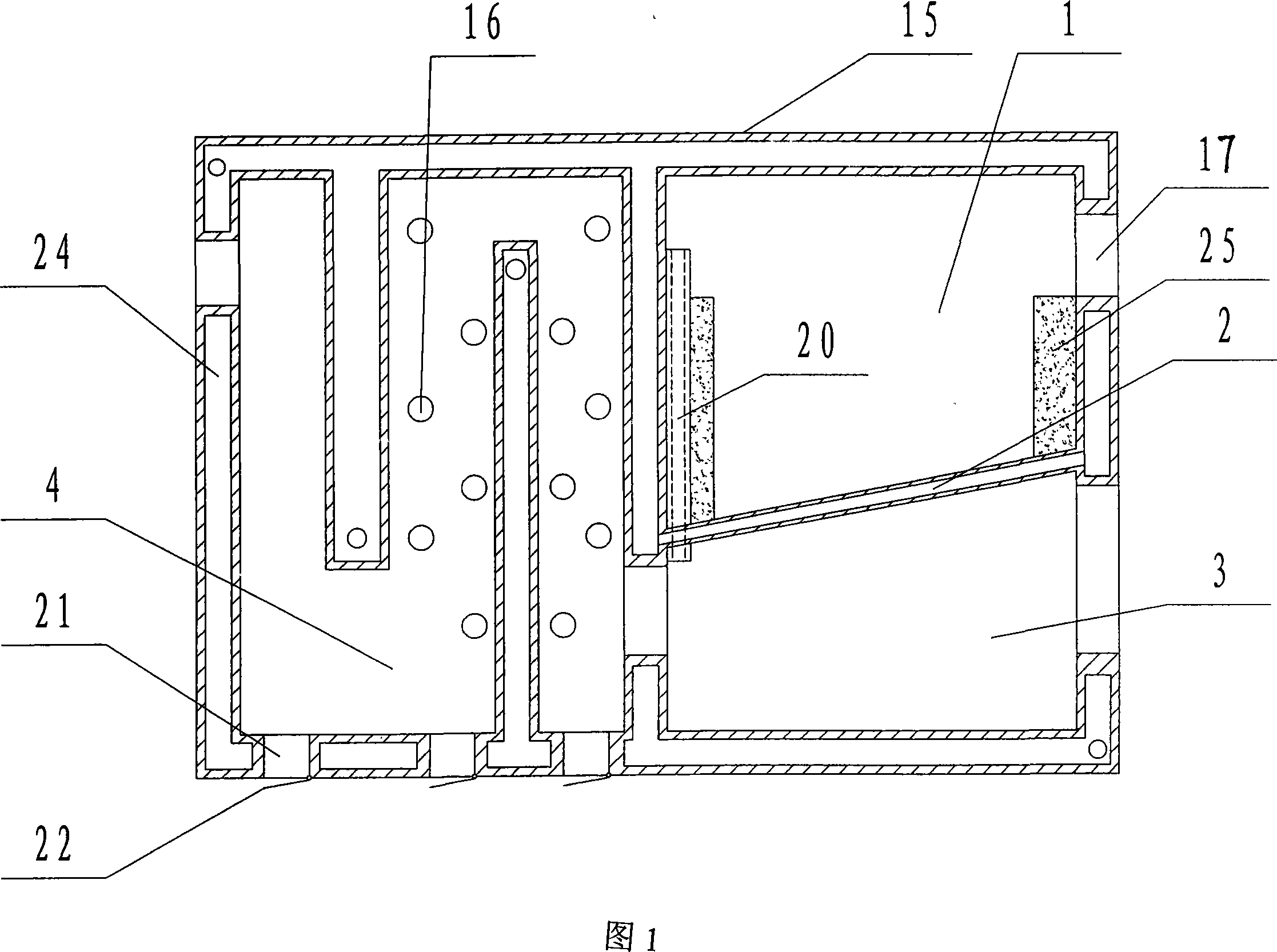
[0017] Example 1: Coal-fired hot air reverse combustion atmospheric pressure boiler, including furnace body 15, combustion chamber 1 inside furnace body 15, furnace bars 2 below combustion chamber 1, ash storage bin 3 below furnace bars 2, and flue 4 , Water barrier 24 is set in body of heater 2. The flue 4 communicates with the ash storage bin 3, and the flue 4 is the heating area. The grate 2 is a tubular structure, and its two ends are connected with water barriers 24 .

[0018] A safety combustion-supporting pipe 20 is arranged in the combustion chamber 1 , the upper part of the safety combustion-supporting pipe 20 extends above the combustion chamber 1 , and the lower end of the safety combustion-supporting pipe 20 extends into the ash storage bin 3 . The arrangement of the safety combustion tube 20 can provide more sufficient oxygen for the secondary combustion.

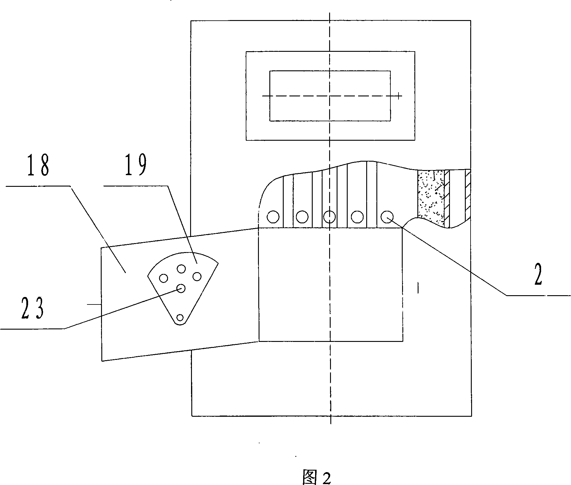
[0019] The ash bin door 18 is arranged at the ash bin mouth of the ash bin 3, and the ash bin door 18 is p...

Example Embodiment

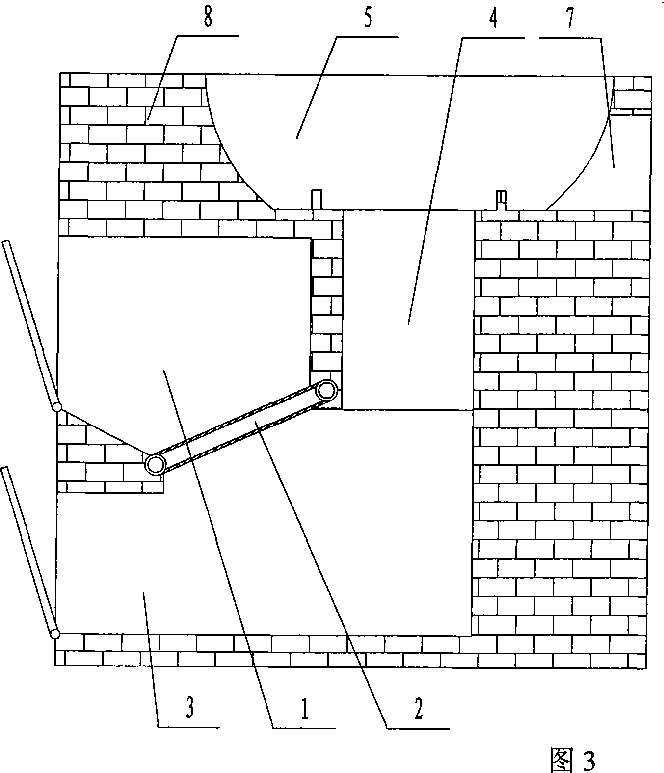
[0021] Embodiment 2: Coal-fired firewood reverse combustion cooker, including the combustion chamber 1 above the furnace bar 2, the ash storage bin 3 below the furnace bar 2, the stove 5 and the chimney 7 connected to one side of the stove 5, and the smoke chamber 5 is installed below the stove 5 Road 4, the flue 4 communicates with the ash storage bin 3. The grate 2 is a tubular structure, and its two ends are connected to the water tank. The upper portion of the flue opposite to the chimney 7 has an exhaust hole 6 .

[0022] After the fuel is burned, the smog containing the incomplete combustion material continues to burn countercurrently from the top of the combustion chamber 1, and the heat also counterflows downward thereupon, and finally enters the stove 5 to heat the pot. Simultaneously the water in the fire bar 2 is also heated for use. The fuel is fully burned throughout the process, with high thermal efficiency and less environmental pollution.

Example Embodiment

[0023] Embodiment 3: a reverse combustion boiler, including a furnace body 15, a combustion chamber 1 inside the furnace body 15, a furnace bar 2 below the combustion chamber 1, and an ashes storage bin 3 below the furnace rod 2, and a water barrier 24 is set in the furnace body 15 . The ash storage bin 3 is connected with the chimney 7 through the lower flue 11 , and the grate 2 is a tubular structure, and its two ends are connected with the water barrier 24 .

[0024] An upper smoking passage 10 is arranged above the combustion chamber 1 to connect with the chimney 7 , and a flip cover 13 is arranged above the upper smoking passage 10 and the lower smoking passage 11 , and the flip cover 13 is installed at the junction of the upper smoking passage 10 and the lower smoking passage 11 through a turning handle 14 .

[0025] The top of the upper smoking passage 10 and the lower smoking passage 11 are connected with the chimney 7 through the connection sleeve 12 .


PUM


Abstract

The invention relates to a hot stream inversion burning device, belonging to a burning device, solving problems that in prior technology common burning devices are provided with insufficiently burning fuel, wasting energy and environment pollution. The hot stream inversion burning device comprises combustor, grate under the combustor, ash storing house, smoke flue and heat collecting region under the grate. The smoke flue is connected with the ash storing house. Said grate is pipe shape and two ends are connected with cycling water container. Uncompleted burning fuel inverses downwards from the top of combustor to carry out secondary burning and then enters into the heat collecting region through the ash storing house. Compared with prior technology, the invention is provided with fuel saving, high heat efficiency and environmental protection. Fog from the combustor is burned in the second time and whereinto fuel in is burned completely so that smoke is eliminated by itself and dust is eliminated by itself. Fuel is burned completely and ash is little.

Description

technical field [0001] The invention belongs to a combustion device, in particular to a hot air flow reversal combustion device. Background technique [0002] Known existing combustion device all comprises combustion chamber, the grate below the combustion chamber, the ash storage bin and the flue below the grate, and the flue is located at the top of the combustion chamber and functions. The fuel usually used in the combustion device is raw coal or firewood. In this way, after the fuel is burned, the smoke goes directly into the chimney, and then is discharged into the atmosphere. Due to the short fuel combustion time and insufficient oxygen supply, the fuel combustion is very incomplete. The smog contains a large amount of incomplete combustion and is directly discharged into the atmosphere without burning, which not only causes low thermal efficiency, wastes fuel, but also pollutes the environment. Contents of the invention [0003] In order to solve the problems of ...

Claims


Application Information

Patent Timeline
IPC IPC(8): F23B70/00
Inventor 李寄陶
Owner 李寄陶
Why Eureka
Try Eureka