Pulsed X-ray for continuous detector correction

A detector and X-ray technology, applied in the field of diagnostic imaging, can solve the problems of large changes in time, unstable photoconductor gain and offset, and achieve the effect of preventing artifacts and reducing thickness

Inactive Publication Date: 2007-11-28
KONINKLIJKE PHILIPS ELECTRONICS NV
View PDF0 Cites 26 Cited by
  • Summary
  • Abstract
  • Description
  • Claims
  • Application Information

AI Technical Summary

Problems solved by technology

However, the gain and offset of photoconductor

Method used


Image

  • Pulsed X-ray for continuous detector correction
  • Pulsed X-ray for continuous detector correction
  • Pulsed X-ray for continuous detector correction

Examples


Embodiment Construction

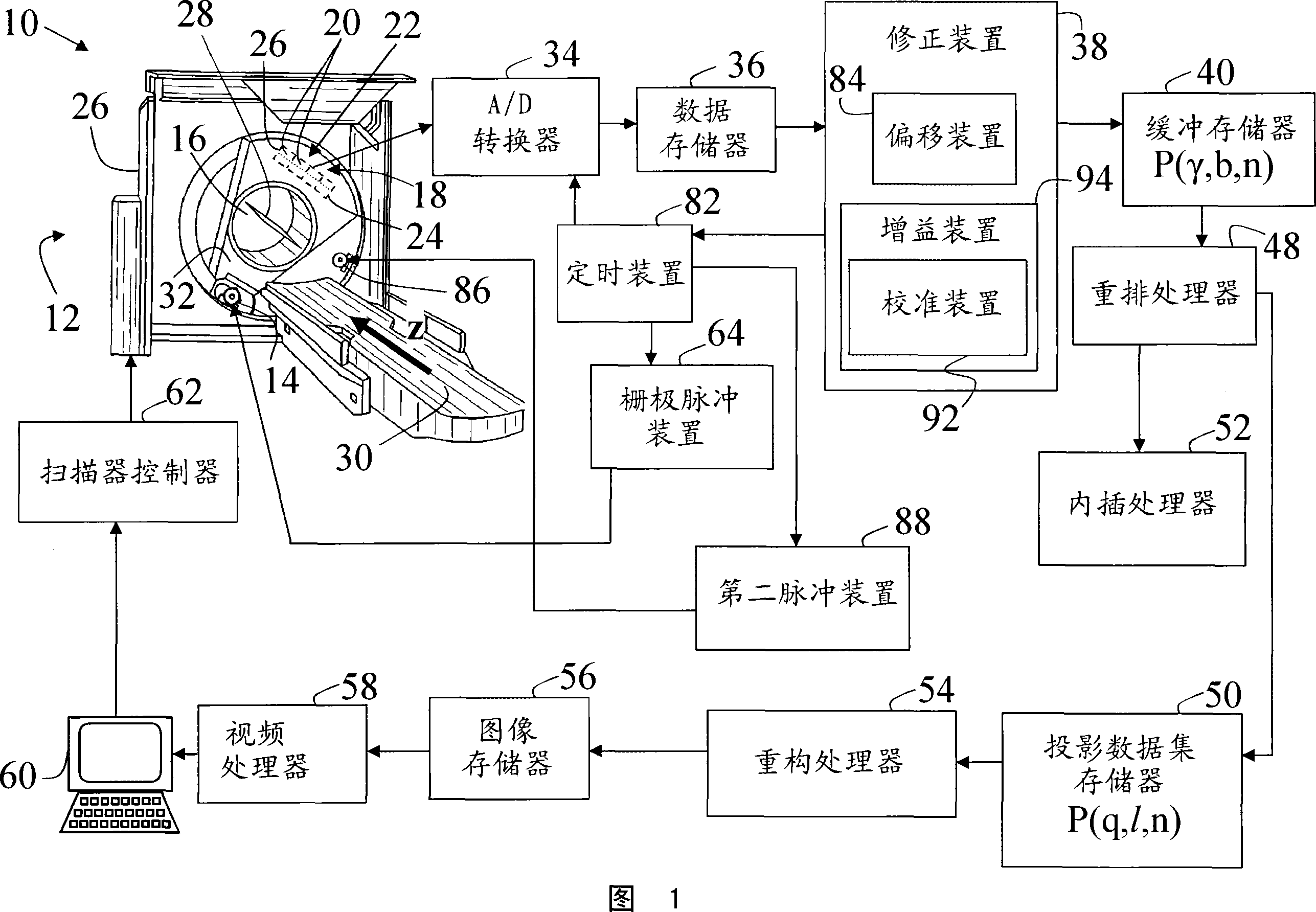
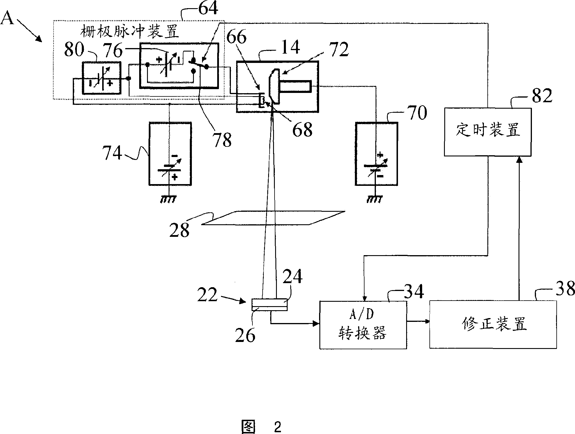
[0035] Referring to FIG. 1 , an imaging system 10 includes a computed tomography scanner 12 that houses or supports a first radiation source 14 that, in one embodiment, projects a beam of radiation onto a region defined by the scanner 12. An x-ray source or x-ray tube in area 16 is inspected. The radiation beam after passing through the examination region 16 is detected by a two-dimensional radiation detector 18 comprising a plurality of detection modules or detection elements 20 arranged to detect the radiation beam after passing through the examination region 16 . Detector 18 includes an X-ray-to-analog signal conversion layer 22 that is characterized by a gain A(t) and / or offset B(t) that generally vary with time. In one embodiment, conversion layer 22 includes an array of scintillation crystals or scintillators or scintillation layer 24 coupled to photodiode array 26 . In another embodiment, the conversion layer 22 comprises a plurality of direct conversion semiconductors...


PUM


Abstract

A radiographic imaging apparatus (10) comprises a primary radiation source (14) which projects a beam of radiation into an examination region (16). A detector (18) converts detected radiation passing through the examination region (16) into electrical detector signals representative of the detected radiation. The detector (18) has at least one temporally changing characteristic such as an offset B(t) or gain A(t). A grid pulse means (64) turns the primary radiation source (14) ON and OFF at a rate between 1000 and 5000 pulses per second, such that at least the offset B(t) is re-measured between 1000 and 5000 times per second and corrected a plurality of times during generation of the detector signals. The gain A(t) is measured by pulsing a second pulsed source (86, 100, 138) of a constant intensity (XRef) with a second pulse means (88). The gain A(t) is re-measured and corrected a plurality of times per second during generation of the detector signals.

Description

technical field [0001] This application relates to diagnostic imaging techniques. It has been found to be particularly suitable for use in computed tomography imaging and will be described with particular reference thereto. Furthermore, it also finds applicability to other imaging devices and methods using X-ray detectors. Background technique [0002] A CT scanner typically includes an x-ray source and an array of x-ray detectors each affixed to diametrically opposite sides of a gantry. During scanning of a patient located in the cavity of the gantry, the gantry rotates about the axis of rotation and the x-ray source emits x-rays during data acquisition during the scan. X-rays are collected by a detector comprising a plurality of detector elements. [0003] Typically, an X-ray detector used in a CT scanner consists of a layer of scintillation crystal connected to an array of silicon photodiodes. Scintillation crystals absorb X-rays passing through the patient and produc...

Claims


Application Information

Patent Timeline
IPC IPC(8): G01T1/29
CPCA61B6/585A61B6/032G01T1/24
Inventor R・P・卢塔M・A・查波B・E・哈伍德R・A・马特森C・J・弗雷托斯
Owner KONINKLIJKE PHILIPS ELECTRONICS NV
Why Eureka
Try Eureka