Sealed battery

A technology for sealing batteries and battery boxes, which is applied to secondary batteries, battery pack components, non-aqueous electrolyte batteries, etc., and can solve problems such as wrong supply of sealing plugs

Active Publication Date: 2007-12-05
MAXELL HLDG LTD
View PDF4 Cites 19 Cited by
  • Summary
  • Abstract
  • Description
  • Claims
  • Application Information

AI Technical Summary

Problems solved by technology

In this case, there is a possibility that a supply error (error) of the sealing plug may occur on the production line.

Method used


Image

  • Sealed battery
  • Sealed battery
  • Sealed battery

Examples


Embodiment Construction

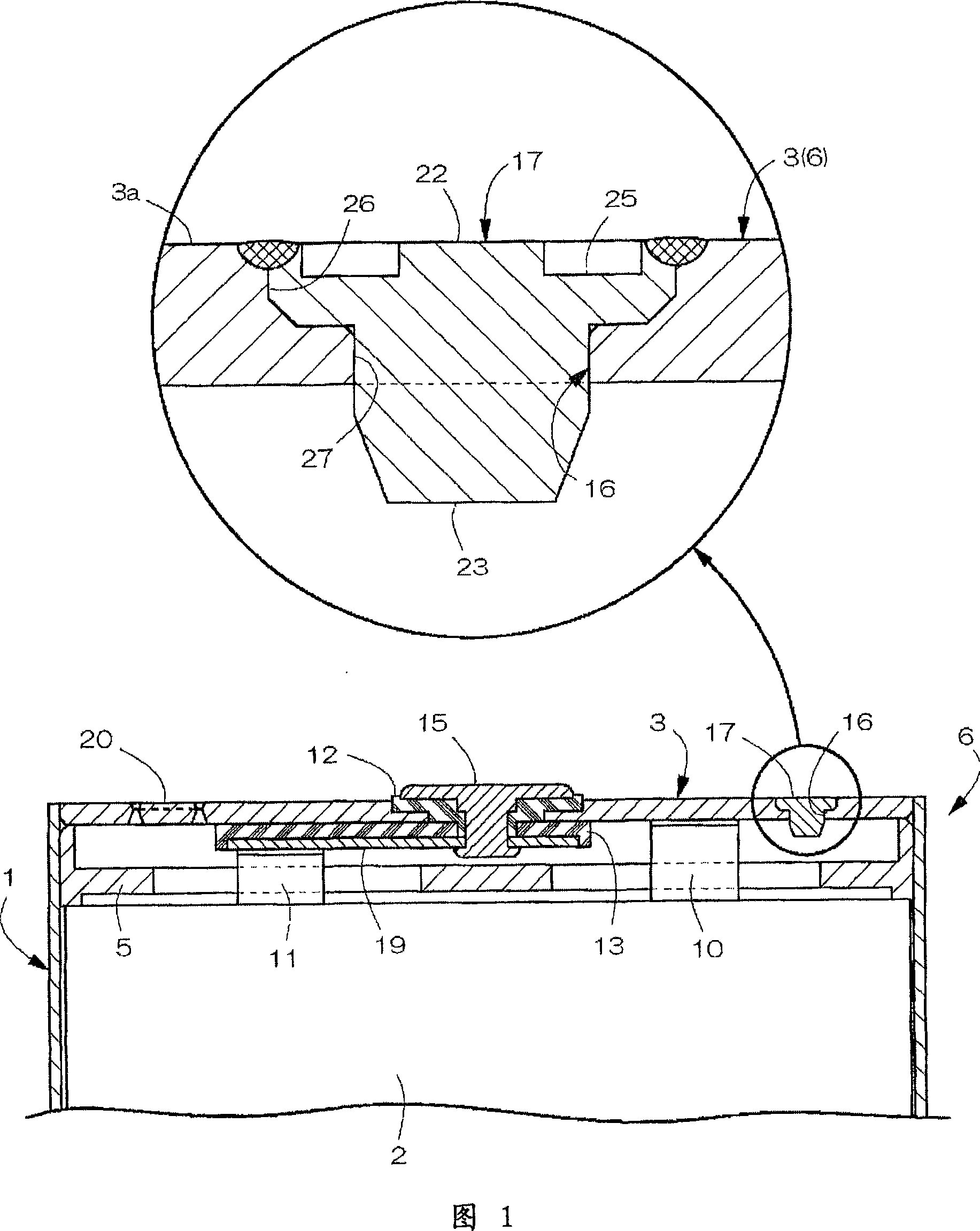
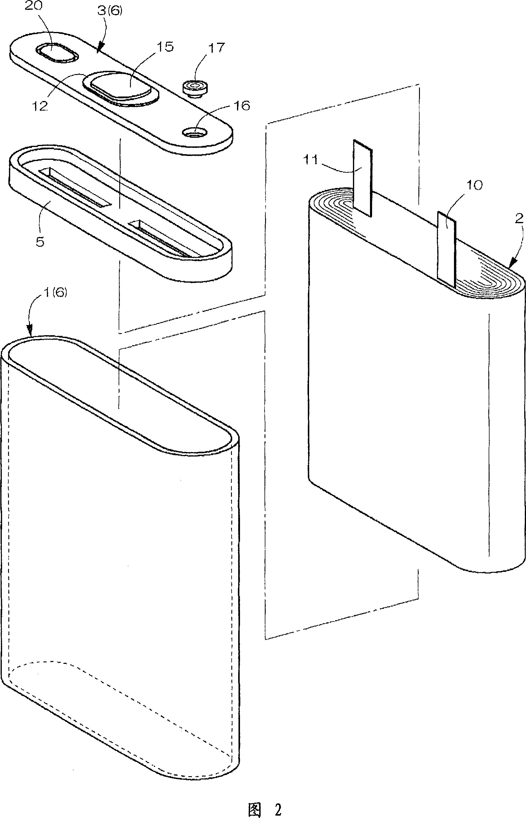
[0031]As shown in Figures 1 and 2, the sealed battery of the present invention includes: a bottomed square tube-shaped battery can 1 with left and right horizontal openings on the top; electrode body 2 and non-aqueous electrolyte contained in the battery can 1 ; a horizontally wide lid 3 that blocks and seals the upper surface of the opening of the battery can 1 ; and a plastic insulator 5 disposed inside the lid 3 . The left and right width of the battery can 1 is 29.0 mm, the vertical height is 46.0 mm, and the front and rear thickness is 4.2 mm. A battery case 6 is formed by the battery can 1 and the cover 3 .

[0032] As shown in FIG. 1 , the electrode body 2 is manufactured by being spirally wound with a strip-shaped separator (separator) inserted between a strip-shaped positive electrode and a strip-shaped negative electrode. The electrode body 2 has a flat shape as shown in FIG. 2 in a wound state. The positive electrode is formed with a positive electrode active mate...


PUM

PropertyMeasurementUnit
widthaaaaaaaaaa
sizeaaaaaaaaaa
sizeaaaaaaaaaa

Abstract

The present invention provides a sealing battery, which prevents electrolyte from remaining in the injecting hole and joints a sealing bolt and injecting hole. After injecting electrolyte into the battery box through the injecting hole, to joint the sealing bolt on the injecting hole to seal the injecting hole. The sealing bolt is arranged with a head and a axis extending from the lower surface of the head. The injecting hole is arranged with a chimeric concave part to table the head of the sealing bolt and a chimeric part of the axis part which is pressed into the sealing bolt. The chimeric part of the injecting hole includes: vertical inner surface part; taper inner surface part with taper surface shaped which turns narrow downwards; and bearing surface part to support the lower surfaceof the head of the sealing bolt. The head of the sealing bolt includes: lower surface; vertical outer surface part which is opposite to the vertical inner surface part of the injecting hole; and taper outer surface part with taper surface shaped which is opposite to the taper inner surface part of the injecting hole and turns narrow downwards.

Description

technical field [0001] The present invention relates to sealed batteries such as lithium ion batteries. Background technique [0002] In patent documents 1 (Japanese Unexamined Patent Publication No. 2000-106156 (FIG. 5)) and 2 (Japanese Patent Laid-Open No. 2002-358948 (FIG. 1)), a method of closing the upper opening of the battery can with a cover is disclosed. A sealed battery in which an electrode body, an electrolyte, etc. are contained in a battery case. In this sealed battery, the electrolyte solution is injected into the battery can from a liquid injection hole provided on the cover, and then a sealing plug is fitted in the liquid injection hole, and the upper end peripheral portion of the sealing plug is slit by using a laser or the like ( seam) is welded on the upper peripheral portion of the liquid injection hole, thereby sealing the liquid injection hole with a sealing plug. [0003] After the electrolytic solution is injected, some electrolytic solution may re...

Claims


Application Information

Patent Timeline
Patent Type & Authority Applications(China)
IPC IPC(8): H01M2/02H01M2/04H01M2/36H01M10/40H01M10/05H01M10/0525H01M10/0566
CPCY02E60/122Y02E60/10H01M10/0525H01M50/645H01M50/15
Inventor 山本真由美藤原义久杣友良树
Owner MAXELL HLDG LTD
Why Eureka
Try Eureka