Control of lattice spacing within crystals

A lattice and crystal technology, applied in the field of lattice spacing control, can solve the problems of uncertain reflection peak position, reduced intensity, increased width, etc., and achieve the effect of dynamic positioning

Inactive Publication Date: 2007-12-05
EASTMAN KODAK CO
View PDF5 Cites 7 Cited by
  • Summary
  • Abstract
  • Description
  • Claims
  • Application Information

AI Technical Summary

Problems solved by technology

This results in increased width, decreased intensity, and uncertain location of reflection peaks
The range of lattice spacing that can be tuned within these systems is limited by the flexibility of the polymer matrix, which limits the wavelength range over which the device can operate

Method used


Image

  • Control of lattice spacing within crystals
  • Control of lattice spacing within crystals
  • Control of lattice spacing within crystals

Examples


Embodiment Construction

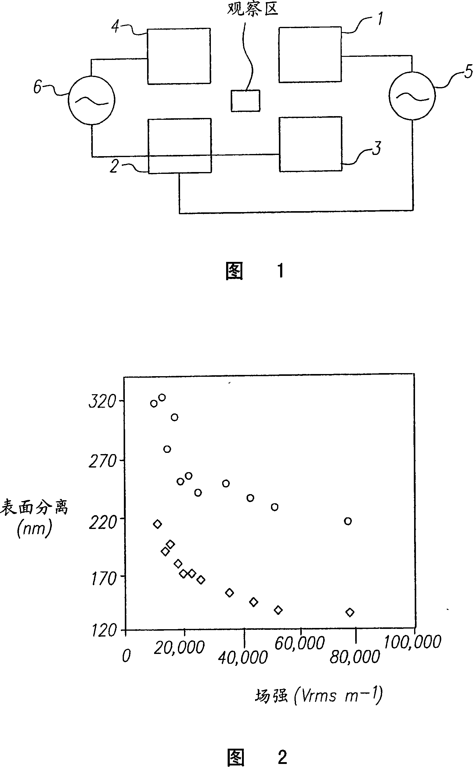
[0020] Figure 1 illustrates a layout of the electrodes used to demonstrate the method of the present invention.

[0021] Four electrodes 1, 2, 3 and 4 are arranged around the observation area. Electrodes 1 and 2 are connected to a signal amplifier 5 . Electrodes 3 and 4 are connected to a signal amplifier 6 . These four electrodes are coplanar. In the experiments performed, the distance between electrodes 1, 4 and 2, 3 was 159 μm. The distance between electrodes 1,3 and 2,4 is 142 μm. However, the gap can be adjusted as desired. A smaller distance means a lower voltage to achieve the desired effect, i.e. about 30000Vm -1 Strength of.

[0022] The electrodes consisted of a 40 nm thick layer of platinum sputter coated on a glass microscope slide. Typically a 10 μL aliquot of the diluted suspension of anionic polystyrene latex particles is placed between the electrodes and covered with a microscope coverslip. In the presence of the suspension, the side-to-side resistance ...


PUM

PropertyMeasurementUnit
particle sizeaaaaaaaaaa

Abstract

A method of creating and controlling the particle spacing of a regular lattice of monodisperse particles or a mixture of monodisperse particles by using an electric field.

Description

field of invention [0001] The invention relates to the field of crystals, in particular to the control of lattice spacing between particles in crystals. Background of the invention [0002] Photonic crystals are known in the prior art to have a wide variety of applications in optoelectronics, lasers, planar lenses, sensors, filters and display devices. A common method for fabricating photonic crystals is to use colloidal self-assembly into colloidal crystals. This self-assembly process can be achieved by a range of different methods such as deposition, centrifugation, filtration, shear alignment or evaporative deposition. It is also known that electric fields can be used to assemble close-packed arrays of colloids. See eg (Electrophoretic assembly of colloidal crystals with optically tunable micropatterns R.C. Hayward, D.A. Saville & I.A. Aksay, Nature, Vol. 404, p. 56, 2000) and references cited therein. In "ElectricField-Reversible Three-Dimensional Colloidal Crystals" ...

Claims


Application Information

Patent Timeline
Patent Type & Authority Applications(China)
IPC IPC(8): G02B6/122C30B5/00G02F1/01G02B6/12G02F1/00
CPCG02B2006/12166G02F2202/32G02F1/00B82Y20/00G02B6/1225
Inventor D·斯诺斯维尔B·文森特C·鲍尔
Owner EASTMAN KODAK CO
Why Eureka
Try Eureka